

JM
John Malsbury
Fri, Jun 22, 2012 6:11 PM
If I might chime in...
If you use the SBX retune feature, this will align all of the phase LOs.
However, variations in other parts of the signal chain (mixers, filters,
etc) will cause slight phase differences across the channels. So, you may
still need to some level of calibration of channel-to-channel phase if you
need them very closely aligned. The phase differences between the channels
will change across temperature and frequency, but not with each re-tune if
you use these timed commands. Calibration requirements are ultimately
driven by the channel-to-channel phase and amplitude requirements of your
application.
Chris, can you explain a little about how this system works? Are you doing
ranging and comms with this system? I've seen similar, multi-channel
optical systems with other customers.
-John
On Fri, Jun 22, 2012 at 10:49 AM, Matt Ettus matt@ettus.com wrote:
To clarify here, as long as all LOs are tuned at the same time, you
will always get the same phase offset. If you retune one, you have to
retune the others simultaneously.
Matt
On Fri, Jun 22, 2012 at 1:58 AM, Christophe ALEXANDRE
christophe.alexandre@cnam.fr wrote:
Hi Josh,
i've read the link :
Using timed commands, multiple frontends can be tuned at a specific time.
This timed-tuning ensures that the phase offsets between VCO/PLL chains
remain constant after each re-tune. See notes below:
a.. There is a random phase offset between any two frontends
b.. This phase offset is different for different LO frequencies
c.. This phase offset remains constant after retuning
a.. Due to divider, WBX phase offset will be randomly +/- 180 deg after
re-tune
d.. This phase offset will drift over time due to thermal and other
characteristics
e.. Periodic calibration will be necessary for phase-coherent
I still don't understand the principle you use. is it a VCO special
?
some questions still remain :
Q1) if i change LO freq from f1 to f2 then back to f1, should i get the
phase offset on f1 ?
Q2) if i turn off the N210s then on, should i get the same offset on the
same freq ?
Q3) if the Q1, Q2 answers are yes, what kind of phase offset precision
should i expect ?
regards.
Christophe ALEXANDRE
Conservatoire National des Arts et Métiers (CNAM)
Laboratoire CEDRIC-LAETITIA
Département EASY
Accès 17-1-32, Case 2D2P10
292 rue Saint Martin
75141 PARIS CEDEX 03
FRANCE
email : christophe.alexandre@cnam.fr
tel. 0140272699
mob. 0651087311
fax. 0140272994
----- Original Message ----- From: "Josh Blum" josh@ettus.com
To: usrp-users@lists.ettus.com
Sent: Thursday, June 21, 2012 5:53 PM
Subject: Re: [USRP-users] LO phase alignment
On 06/21/2012 08:48 AM, Christophe ALEXANDRE wrote:
hi John,
i have already read this app note (in fact, i have started with it).
I've only seen a star after phase on table 2 for SBX but no more info.
what is the basic principle used to solve the phase alignment problem ?
can i use this new feature using gnuradio ?
do you have any example (even C++ example) showing how to use it ?
If I might chime in...
If you use the SBX retune feature, this will align all of the phase LOs.
However, variations in other parts of the signal chain (mixers, filters,
etc) will cause slight phase differences across the channels. So, you may
still need to some level of calibration of channel-to-channel phase if you
need them very closely aligned. The phase differences between the channels
will change across temperature and frequency, but not with each re-tune if
you use these timed commands. Calibration requirements are ultimately
driven by the channel-to-channel phase and amplitude requirements of your
application.
Chris, can you explain a little about how this system works? Are you doing
ranging and comms with this system? I've seen similar, multi-channel
optical systems with other customers.
-John
On Fri, Jun 22, 2012 at 10:49 AM, Matt Ettus <matt@ettus.com> wrote:
> To clarify here, as long as all LOs are tuned at the same time, you
> will always get the same phase offset. If you retune one, you have to
> retune the others simultaneously.
>
> Matt
>
> On Fri, Jun 22, 2012 at 1:58 AM, Christophe ALEXANDRE
> <christophe.alexandre@cnam.fr> wrote:
> > Hi Josh,
> >
> > i've read the link :
> >
> > Using timed commands, multiple frontends can be tuned at a specific time.
> > This timed-tuning ensures that the phase offsets between VCO/PLL chains
> will
> > remain constant after each re-tune. See notes below:
> > a.. There is a random phase offset between any two frontends
> > b.. This phase offset is different for different LO frequencies
> > c.. This phase offset remains constant after retuning
> > a.. Due to divider, WBX phase offset will be randomly +/- 180 deg after
> > re-tune
> > d.. This phase offset will drift over time due to thermal and other
> > characteristics
> > e.. Periodic calibration will be necessary for phase-coherent
> applications
> > I still don't understand the principle you use. is it a VCO special
> property
> > ?
> >
> > some questions still remain :
> >
> > Q1) if i change LO freq from f1 to f2 then back to f1, should i get the
> same
> > phase offset on f1 ?
> >
> > Q2) if i turn off the N210s then on, should i get the same offset on the
> > same freq ?
> >
> > Q3) if the Q1, Q2 answers are yes, what kind of phase offset precision
> > should i expect ?
> >
> >
> >
> > regards.
> >
> >
> > Christophe ALEXANDRE
> > Conservatoire National des Arts et Métiers (CNAM)
> > Laboratoire CEDRIC-LAETITIA
> > Département EASY
> > Accès 17-1-32, Case 2D2P10
> > 292 rue Saint Martin
> > 75141 PARIS CEDEX 03
> > FRANCE
> > email : christophe.alexandre@cnam.fr
> > tel. 0140272699
> > mob. 0651087311
> > fax. 0140272994
> >
> >
> > ----- Original Message ----- From: "Josh Blum" <josh@ettus.com>
> > To: <usrp-users@lists.ettus.com>
> > Sent: Thursday, June 21, 2012 5:53 PM
> >
> > Subject: Re: [USRP-users] LO phase alignment
> >
> >
> >>
> >>
> >> On 06/21/2012 08:48 AM, Christophe ALEXANDRE wrote:
> >>>
> >>> hi John,
> >>>
> >>> i have already read this app note (in fact, i have started with it).
> >>> I've only seen a star after phase on table 2 for SBX but no more info.
> >>>
> >>> what is the basic principle used to solve the phase alignment problem ?
> >>>
> >>
> >> Does this example help:
> >>
> >>
> http://files.ettus.com/uhd_docs/manual/html/sync.html#align-los-in-the-front-end-sbx-wbx-n-series
> >>
> >>> can i use this new feature using gnuradio ?
> >>>
> >>
> >> Yes
> >>
> >>> do you have any example (even C++ example) showing how to use it ?
> >>>
> >>
> >> Link above.
> >>
> >> -josh
> >>
> >> _______________________________________________
> >> USRP-users mailing list
> >> USRP-users@lists.ettus.com
> >> http://lists.ettus.com/mailman/listinfo/usrp-users_lists.ettus.com
> >
> >
> >
> >
> > _______________________________________________
> > USRP-users mailing list
> > USRP-users@lists.ettus.com
> > http://lists.ettus.com/mailman/listinfo/usrp-users_lists.ettus.com
>
> _______________________________________________
> USRP-users mailing list
> USRP-users@lists.ettus.com
> http://lists.ettus.com/mailman/listinfo/usrp-users_lists.ettus.com
>
AC
ALEXANDRE Christophe
Fri, Jun 22, 2012 8:12 PM
Hi John,
i need to measure a phase difference between two photodiodes
very precisely. I think it's possible with with 2 N210, but i'm
used to use it for radio application under Matlab and not for
optical application.
I've already designed a telemetry system for very precise distance
measurement (better than 10^-10), but directly with an ML605 +
FMC150 + external mixers and a single LO, the same for emission
and reception.
This time, those guys asked me to realize the electronic part
of a laser telemeter, optimized for low cost and 10^-7 accuracy
(the effect of air temperature will be solved later using 2 lasers
with different wavelength, so we will use 2 telemeters in one system).
the basic principle is the following :
the TX laser is amplitude modulated with a 3.00005 GHz carrier.
on both photodiodes, RX signals are demodulated with a 3 GHz LO and the phase
difference between both 50 kHz sinus is measured.
the distance measurement is done in 2 steps :
- put an optical reflector at distance L0. this is the 0 reference.
- put an optical reflector at distance Lx. this is the unkown distance.
the phase difference doesn't give you directly the distance L because
at 3 GHz, the wavelength is about 10 cm in the air. So the distance is equivalent
to a difference 2.k.pi + deltaphi, and you only get deltaphi. One elegant solution
to get k is to find f1 where deltaphi = 0, increase freq and find the next deltaphi = 0
that will give you f2. then L=c/(f2-f1).
the principle is easy to understand, the optical part is not very complicated
but a 10^-7 accuracy in not so easy to get.
when the optical guys told me about what they want, i immediatly thought
about a mimo receiver (i'm also working on antenna processing algorithms)
but with phase alignment.
i tried to use 2 N210 linked with a MIMO cable, the master being external referenced
with a rubidium clock. The master generate the carrier and receive the first photodiode
signal, the slave receive the second photodiode signal.
At first, i linked directly TX with RX1 via an attenuator and put an SMA cable between
RX1 and RX2 (quick and dirty, only to get a delay). i calculate phase difference
(i use GRC because Matlab doesn't support external ref nor mimo cable) and put
a wxgui slider on carrier frequency. And of course, when i change freq from f1 to f2
then back to f1, the phase difference is not the same. So i can't use this "as is" to
measure the distance.
From your explanations, i think it could be done if the phase difference between LOs is
the same because the calibration process is included in the measure but :
-
when you say i will get the same phase offset on each LO, i wonder about
the precision (what do you call the same offset ?).
-
how fast is the retuning ? regarding this point, i think tuning offset can help a lot.
i can find coarsely deltaphi = 0 then refine with the DSP offset.
i hope the process is more clear now.
Do you think the principle is correct ?
regards.
Christophe ALEXANDRE
Conservatoire National des Arts et Métiers (CNAM)
Laboratoire CEDRIC-LAETITIA
Département EASY
Accès 17-1-32, Case 2D2P10
292 rue Saint Martin
75141 PARIS CEDEX 03
FRANCE
email : christophe.alexandre@cnam.fr
tel. 0140272699
mob. 0651087311
fax. 0140272994
----- Original Message -----
From: John Malsbury
To: usrp-users@lists.ettus.com
Sent: Friday, June 22, 2012 8:11 PM
Subject: Re: [USRP-users] LO phase alignment
If I might chime in...
If you use the SBX retune feature, this will align all of the phase LOs. However, variations in other parts of the signal chain (mixers, filters, etc) will cause slight phase differences across the channels. So, you may still need to some level of calibration of channel-to-channel phase if you need them very closely aligned. The phase differences between the channels will change across temperature and frequency, but not with each re-tune if you use these timed commands. Calibration requirements are ultimately driven by the channel-to-channel phase and amplitude requirements of your application.
Chris, can you explain a little about how this system works? Are you doing ranging and comms with this system? I've seen similar, multi-channel optical systems with other customers.
-John
On Fri, Jun 22, 2012 at 10:49 AM, Matt Ettus matt@ettus.com wrote:
To clarify here, as long as all LOs are tuned at the same time, you
will always get the same phase offset. If you retune one, you have to
retune the others simultaneously.
Matt
On Fri, Jun 22, 2012 at 1:58 AM, Christophe ALEXANDRE
<christophe.alexandre@cnam.fr> wrote:
Hi Josh,
i've read the link :
Using timed commands, multiple frontends can be tuned at a specific time.
This timed-tuning ensures that the phase offsets between VCO/PLL chains will
remain constant after each re-tune. See notes below:
a.. There is a random phase offset between any two frontends
b.. This phase offset is different for different LO frequencies
c.. This phase offset remains constant after retuning
a.. Due to divider, WBX phase offset will be randomly +/- 180 deg after
re-tune
d.. This phase offset will drift over time due to thermal and other
characteristics
e.. Periodic calibration will be necessary for phase-coherent applications
I still don't understand the principle you use. is it a VCO special property
?
some questions still remain :
Q1) if i change LO freq from f1 to f2 then back to f1, should i get the same
phase offset on f1 ?
Q2) if i turn off the N210s then on, should i get the same offset on the
same freq ?
Q3) if the Q1, Q2 answers are yes, what kind of phase offset precision
should i expect ?
regards.
Christophe ALEXANDRE
Conservatoire National des Arts et Métiers (CNAM)
Laboratoire CEDRIC-LAETITIA
Département EASY
Accès 17-1-32, Case 2D2P10
292 rue Saint Martin
75141 PARIS CEDEX 03
FRANCE
email : christophe.alexandre@cnam.fr
tel. 0140272699
mob. 0651087311
fax. 0140272994
----- Original Message ----- From: "Josh Blum" josh@ettus.com
To: usrp-users@lists.ettus.com
Sent: Thursday, June 21, 2012 5:53 PM
Subject: Re: [USRP-users] LO phase alignment
On 06/21/2012 08:48 AM, Christophe ALEXANDRE wrote:
hi John,
i have already read this app note (in fact, i have started with it).
I've only seen a star after phase on table 2 for SBX but no more info.
what is the basic principle used to solve the phase alignment problem ?
can i use this new feature using gnuradio ?
do you have any example (even C++ example) showing how to use it ?
Hi John,
i need to measure a phase difference between two photodiodes
very precisely. I think it's possible with with 2 N210, but i'm
used to use it for radio application under Matlab and not for
optical application.
I've already designed a telemetry system for very precise distance
measurement (better than 10^-10), but directly with an ML605 +
FMC150 + external mixers and a single LO, the same for emission
and reception.
This time, those guys asked me to realize the electronic part
of a laser telemeter, optimized for low cost and 10^-7 accuracy
(the effect of air temperature will be solved later using 2 lasers
with different wavelength, so we will use 2 telemeters in one system).
the basic principle is the following :
the TX laser is amplitude modulated with a 3.00005 GHz carrier.
on both photodiodes, RX signals are demodulated with a 3 GHz LO and the phase
difference between both 50 kHz sinus is measured.
the distance measurement is done in 2 steps :
1) put an optical reflector at distance L0. this is the 0 reference.
2) put an optical reflector at distance Lx. this is the unkown distance.
the phase difference doesn't give you directly the distance L because
at 3 GHz, the wavelength is about 10 cm in the air. So the distance is equivalent
to a difference 2.k.pi + deltaphi, and you only get deltaphi. One elegant solution
to get k is to find f1 where deltaphi = 0, increase freq and find the next deltaphi = 0
that will give you f2. then L=c/(f2-f1).
the principle is easy to understand, the optical part is not very complicated
but a 10^-7 accuracy in not so easy to get.
when the optical guys told me about what they want, i immediatly thought
about a mimo receiver (i'm also working on antenna processing algorithms)
but with phase alignment.
i tried to use 2 N210 linked with a MIMO cable, the master being external referenced
with a rubidium clock. The master generate the carrier and receive the first photodiode
signal, the slave receive the second photodiode signal.
At first, i linked directly TX with RX1 via an attenuator and put an SMA cable between
RX1 and RX2 (quick and dirty, only to get a delay). i calculate phase difference
(i use GRC because Matlab doesn't support external ref nor mimo cable) and put
a wxgui slider on carrier frequency. And of course, when i change freq from f1 to f2
then back to f1, the phase difference is not the same. So i can't use this "as is" to
measure the distance.
>From your explanations, i think it could be done if the phase difference between LOs is
the same because the calibration process is included in the measure but :
1) when you say i will get the same phase offset on each LO, i wonder about
the precision (what do you call the same offset ?).
2) how fast is the retuning ? regarding this point, i think tuning offset can help a lot.
i can find coarsely deltaphi = 0 then refine with the DSP offset.
i hope the process is more clear now.
Do you think the principle is correct ?
regards.
Christophe ALEXANDRE
Conservatoire National des Arts et Métiers (CNAM)
Laboratoire CEDRIC-LAETITIA
Département EASY
Accès 17-1-32, Case 2D2P10
292 rue Saint Martin
75141 PARIS CEDEX 03
FRANCE
email : christophe.alexandre@cnam.fr
tel. 0140272699
mob. 0651087311
fax. 0140272994
----- Original Message -----
From: John Malsbury
To: usrp-users@lists.ettus.com
Sent: Friday, June 22, 2012 8:11 PM
Subject: Re: [USRP-users] LO phase alignment
If I might chime in...
If you use the SBX retune feature, this will align all of the phase LOs. However, variations in other parts of the signal chain (mixers, filters, etc) will cause slight phase differences across the channels. So, you may still need to some level of calibration of channel-to-channel phase if you need them very closely aligned. The phase differences between the channels will change across temperature and frequency, but not with each re-tune if you use these timed commands. Calibration requirements are ultimately driven by the channel-to-channel phase and amplitude requirements of your application.
Chris, can you explain a little about how this system works? Are you doing ranging and comms with this system? I've seen similar, multi-channel optical systems with other customers.
-John
On Fri, Jun 22, 2012 at 10:49 AM, Matt Ettus <matt@ettus.com> wrote:
To clarify here, as long as all LOs are tuned at the same time, you
will always get the same phase offset. If you retune one, you have to
retune the others simultaneously.
Matt
On Fri, Jun 22, 2012 at 1:58 AM, Christophe ALEXANDRE
<christophe.alexandre@cnam.fr> wrote:
> Hi Josh,
>
> i've read the link :
>
> Using timed commands, multiple frontends can be tuned at a specific time.
> This timed-tuning ensures that the phase offsets between VCO/PLL chains will
> remain constant after each re-tune. See notes below:
> a.. There is a random phase offset between any two frontends
> b.. This phase offset is different for different LO frequencies
> c.. This phase offset remains constant after retuning
> a.. Due to divider, WBX phase offset will be randomly +/- 180 deg after
> re-tune
> d.. This phase offset will drift over time due to thermal and other
> characteristics
> e.. Periodic calibration will be necessary for phase-coherent applications
> I still don't understand the principle you use. is it a VCO special property
> ?
>
> some questions still remain :
>
> Q1) if i change LO freq from f1 to f2 then back to f1, should i get the same
> phase offset on f1 ?
>
> Q2) if i turn off the N210s then on, should i get the same offset on the
> same freq ?
>
> Q3) if the Q1, Q2 answers are yes, what kind of phase offset precision
> should i expect ?
>
>
>
> regards.
>
>
> Christophe ALEXANDRE
> Conservatoire National des Arts et Métiers (CNAM)
> Laboratoire CEDRIC-LAETITIA
> Département EASY
> Accès 17-1-32, Case 2D2P10
> 292 rue Saint Martin
> 75141 PARIS CEDEX 03
> FRANCE
> email : christophe.alexandre@cnam.fr
> tel. 0140272699
> mob. 0651087311
> fax. 0140272994
>
>
> ----- Original Message ----- From: "Josh Blum" <josh@ettus.com>
> To: <usrp-users@lists.ettus.com>
> Sent: Thursday, June 21, 2012 5:53 PM
>
> Subject: Re: [USRP-users] LO phase alignment
>
>
>>
>>
>> On 06/21/2012 08:48 AM, Christophe ALEXANDRE wrote:
>>>
>>> hi John,
>>>
>>> i have already read this app note (in fact, i have started with it).
>>> I've only seen a star after phase on table 2 for SBX but no more info.
>>>
>>> what is the basic principle used to solve the phase alignment problem ?
>>>
>>
>> Does this example help:
>>
>> http://files.ettus.com/uhd_docs/manual/html/sync.html#align-los-in-the-front-end-sbx-wbx-n-series
>>
>>> can i use this new feature using gnuradio ?
>>>
>>
>> Yes
>>
>>> do you have any example (even C++ example) showing how to use it ?
>>>
>>
>> Link above.
>>
>> -josh
>>
>> _______________________________________________
>> USRP-users mailing list
>> USRP-users@lists.ettus.com
>> http://lists.ettus.com/mailman/listinfo/usrp-users_lists.ettus.com
>
>
>
>
> _______________________________________________
> USRP-users mailing list
> USRP-users@lists.ettus.com
> http://lists.ettus.com/mailman/listinfo/usrp-users_lists.ettus.com
_______________________________________________
USRP-users mailing list
USRP-users@lists.ettus.com
http://lists.ettus.com/mailman/listinfo/usrp-users_lists.ettus.com
------------------------------------------------------------------------------
_______________________________________________
USRP-users mailing list
USRP-users@lists.ettus.com
http://lists.ettus.com/mailman/listinfo/usrp-users_lists.ettus.com
CA
Christophe ALEXANDRE
Wed, Jul 11, 2012 4:45 PM
hi all,
i'm reading the application note :
Synchronisation and MIMO capability with USRP Devices
from ettus. I use N210 + SBX.
i can reproduce the flowgraph on figure 5 without problem.
Now, i want to replace the RF signal generator on figure 4
using the master N210 in emission mode and reception mode.
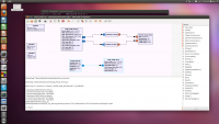
Here is the flowgraph :
As you can see, there is an error message and when i run the flowgraph,
the master in in emission mode only and the slave do nothing.
where is my mistake ?
regards.
Christophe ALEXANDRE
Conservatoire National des Arts et Métiers (CNAM)
Laboratoire CEDRIC-LAETITIA
Département EASY
Accès 11B niveau -1, Case 2D2P10
292 rue Saint Martin
75141 PARIS CEDEX 03
FRANCE
email : christophe.alexandre@cnam.fr
tel. 0140272699
mob. 0651087311
fax. 0140272994
----- Original Message -----
From: ALEXANDRE Christophe
To: John Malsbury ; usrp-users@lists.ettus.com
Sent: Friday, June 22, 2012 10:12 PM
Subject: Re: [USRP-users] LO phase alignment
Hi John,
i need to measure a phase difference between two photodiodes
very precisely. I think it's possible with with 2 N210, but i'm
used to use it for radio application under Matlab and not for
optical application.
I've already designed a telemetry system for very precise distance
measurement (better than 10^-10), but directly with an ML605 +
FMC150 + external mixers and a single LO, the same for emission
and reception.
This time, those guys asked me to realize the electronic part
of a laser telemeter, optimized for low cost and 10^-7 accuracy
(the effect of air temperature will be solved later using 2 lasers
with different wavelength, so we will use 2 telemeters in one system).
the basic principle is the following :
the TX laser is amplitude modulated with a 3.00005 GHz carrier.
on both photodiodes, RX signals are demodulated with a 3 GHz LO and the phase
difference between both 50 kHz sinus is measured.
the distance measurement is done in 2 steps :
- put an optical reflector at distance L0. this is the 0 reference.
- put an optical reflector at distance Lx. this is the unkown distance.
the phase difference doesn't give you directly the distance L because
at 3 GHz, the wavelength is about 10 cm in the air. So the distance is equivalent
to a difference 2.k.pi + deltaphi, and you only get deltaphi. One elegant solution
to get k is to find f1 where deltaphi = 0, increase freq and find the next deltaphi = 0
that will give you f2. then L=c/(f2-f1).
the principle is easy to understand, the optical part is not very complicated
but a 10^-7 accuracy in not so easy to get.
when the optical guys told me about what they want, i immediatly thought
about a mimo receiver (i'm also working on antenna processing algorithms)
but with phase alignment.
i tried to use 2 N210 linked with a MIMO cable, the master being external referenced
with a rubidium clock. The master generate the carrier and receive the first photodiode
signal, the slave receive the second photodiode signal.
At first, i linked directly TX with RX1 via an attenuator and put an SMA cable between
RX1 and RX2 (quick and dirty, only to get a delay). i calculate phase difference
(i use GRC because Matlab doesn't support external ref nor mimo cable) and put
a wxgui slider on carrier frequency. And of course, when i change freq from f1 to f2
then back to f1, the phase difference is not the same. So i can't use this "as is" to
measure the distance.
From your explanations, i think it could be done if the phase difference between LOs is
the same because the calibration process is included in the measure but :
-
when you say i will get the same phase offset on each LO, i wonder about
the precision (what do you call the same offset ?).
-
how fast is the retuning ? regarding this point, i think tuning offset can help a lot.
i can find coarsely deltaphi = 0 then refine with the DSP offset.
i hope the process is more clear now.
Do you think the principle is correct ?
regards.
Christophe ALEXANDRE
Conservatoire National des Arts et Métiers (CNAM)
Laboratoire CEDRIC-LAETITIA
Département EASY
Accès 17-1-32, Case 2D2P10
292 rue Saint Martin
75141 PARIS CEDEX 03
FRANCE
email : christophe.alexandre@cnam.fr
tel. 0140272699
mob. 0651087311
fax. 0140272994
----- Original Message -----
From: John Malsbury
To: usrp-users@lists.ettus.com
Sent: Friday, June 22, 2012 8:11 PM
Subject: Re: [USRP-users] LO phase alignment
If I might chime in...
If you use the SBX retune feature, this will align all of the phase LOs. However, variations in other parts of the signal chain (mixers, filters, etc) will cause slight phase differences across the channels. So, you may still need to some level of calibration of channel-to-channel phase if you need them very closely aligned. The phase differences between the channels will change across temperature and frequency, but not with each re-tune if you use these timed commands. Calibration requirements are ultimately driven by the channel-to-channel phase and amplitude requirements of your application.
Chris, can you explain a little about how this system works? Are you doing ranging and comms with this system? I've seen similar, multi-channel optical systems with other customers.
-John
On Fri, Jun 22, 2012 at 10:49 AM, Matt Ettus <matt@ettus.com> wrote:
To clarify here, as long as all LOs are tuned at the same time, you
will always get the same phase offset. If you retune one, you have to
retune the others simultaneously.
Matt
On Fri, Jun 22, 2012 at 1:58 AM, Christophe ALEXANDRE
<christophe.alexandre@cnam.fr> wrote:
Hi Josh,
i've read the link :
Using timed commands, multiple frontends can be tuned at a specific time.
This timed-tuning ensures that the phase offsets between VCO/PLL chains will
remain constant after each re-tune. See notes below:
a.. There is a random phase offset between any two frontends
b.. This phase offset is different for different LO frequencies
c.. This phase offset remains constant after retuning
a.. Due to divider, WBX phase offset will be randomly +/- 180 deg after
re-tune
d.. This phase offset will drift over time due to thermal and other
characteristics
e.. Periodic calibration will be necessary for phase-coherent applications
I still don't understand the principle you use. is it a VCO special property
?
some questions still remain :
Q1) if i change LO freq from f1 to f2 then back to f1, should i get the same
phase offset on f1 ?
Q2) if i turn off the N210s then on, should i get the same offset on the
same freq ?
Q3) if the Q1, Q2 answers are yes, what kind of phase offset precision
should i expect ?
regards.
Christophe ALEXANDRE
Conservatoire National des Arts et Métiers (CNAM)
Laboratoire CEDRIC-LAETITIA
Département EASY
Accès 17-1-32, Case 2D2P10
292 rue Saint Martin
75141 PARIS CEDEX 03
FRANCE
email : christophe.alexandre@cnam.fr
tel. 0140272699
mob. 0651087311
fax. 0140272994
----- Original Message ----- From: "Josh Blum" josh@ettus.com
To: usrp-users@lists.ettus.com
Sent: Thursday, June 21, 2012 5:53 PM
Subject: Re: [USRP-users] LO phase alignment
On 06/21/2012 08:48 AM, Christophe ALEXANDRE wrote:
hi John,
i have already read this app note (in fact, i have started with it).
I've only seen a star after phase on table 2 for SBX but no more info.
what is the basic principle used to solve the phase alignment problem ?
can i use this new feature using gnuradio ?
do you have any example (even C++ example) showing how to use it ?
hi all,
i'm reading the application note :
Synchronisation and MIMO capability with USRP Devices
from ettus. I use N210 + SBX.
i can reproduce the flowgraph on figure 5 without problem.
Now, i want to replace the RF signal generator on figure 4
using the master N210 in emission mode and reception mode.
Here is the flowgraph :
As you can see, there is an error message and when i run the flowgraph,
the master in in emission mode only and the slave do nothing.
where is my mistake ?
regards.
Christophe ALEXANDRE
Conservatoire National des Arts et Métiers (CNAM)
Laboratoire CEDRIC-LAETITIA
Département EASY
Accès 11B niveau -1, Case 2D2P10
292 rue Saint Martin
75141 PARIS CEDEX 03
FRANCE
email : christophe.alexandre@cnam.fr
tel. 0140272699
mob. 0651087311
fax. 0140272994
----- Original Message -----
From: ALEXANDRE Christophe
To: John Malsbury ; usrp-users@lists.ettus.com
Sent: Friday, June 22, 2012 10:12 PM
Subject: Re: [USRP-users] LO phase alignment
Hi John,
i need to measure a phase difference between two photodiodes
very precisely. I think it's possible with with 2 N210, but i'm
used to use it for radio application under Matlab and not for
optical application.
I've already designed a telemetry system for very precise distance
measurement (better than 10^-10), but directly with an ML605 +
FMC150 + external mixers and a single LO, the same for emission
and reception.
This time, those guys asked me to realize the electronic part
of a laser telemeter, optimized for low cost and 10^-7 accuracy
(the effect of air temperature will be solved later using 2 lasers
with different wavelength, so we will use 2 telemeters in one system).
the basic principle is the following :
the TX laser is amplitude modulated with a 3.00005 GHz carrier.
on both photodiodes, RX signals are demodulated with a 3 GHz LO and the phase
difference between both 50 kHz sinus is measured.
the distance measurement is done in 2 steps :
1) put an optical reflector at distance L0. this is the 0 reference.
2) put an optical reflector at distance Lx. this is the unkown distance.
the phase difference doesn't give you directly the distance L because
at 3 GHz, the wavelength is about 10 cm in the air. So the distance is equivalent
to a difference 2.k.pi + deltaphi, and you only get deltaphi. One elegant solution
to get k is to find f1 where deltaphi = 0, increase freq and find the next deltaphi = 0
that will give you f2. then L=c/(f2-f1).
the principle is easy to understand, the optical part is not very complicated
but a 10^-7 accuracy in not so easy to get.
when the optical guys told me about what they want, i immediatly thought
about a mimo receiver (i'm also working on antenna processing algorithms)
but with phase alignment.
i tried to use 2 N210 linked with a MIMO cable, the master being external referenced
with a rubidium clock. The master generate the carrier and receive the first photodiode
signal, the slave receive the second photodiode signal.
At first, i linked directly TX with RX1 via an attenuator and put an SMA cable between
RX1 and RX2 (quick and dirty, only to get a delay). i calculate phase difference
(i use GRC because Matlab doesn't support external ref nor mimo cable) and put
a wxgui slider on carrier frequency. And of course, when i change freq from f1 to f2
then back to f1, the phase difference is not the same. So i can't use this "as is" to
measure the distance.
From your explanations, i think it could be done if the phase difference between LOs is
the same because the calibration process is included in the measure but :
1) when you say i will get the same phase offset on each LO, i wonder about
the precision (what do you call the same offset ?).
2) how fast is the retuning ? regarding this point, i think tuning offset can help a lot.
i can find coarsely deltaphi = 0 then refine with the DSP offset.
i hope the process is more clear now.
Do you think the principle is correct ?
regards.
Christophe ALEXANDRE
Conservatoire National des Arts et Métiers (CNAM)
Laboratoire CEDRIC-LAETITIA
Département EASY
Accès 17-1-32, Case 2D2P10
292 rue Saint Martin
75141 PARIS CEDEX 03
FRANCE
email : christophe.alexandre@cnam.fr
tel. 0140272699
mob. 0651087311
fax. 0140272994
----- Original Message -----
From: John Malsbury
To: usrp-users@lists.ettus.com
Sent: Friday, June 22, 2012 8:11 PM
Subject: Re: [USRP-users] LO phase alignment
If I might chime in...
If you use the SBX retune feature, this will align all of the phase LOs. However, variations in other parts of the signal chain (mixers, filters, etc) will cause slight phase differences across the channels. So, you may still need to some level of calibration of channel-to-channel phase if you need them very closely aligned. The phase differences between the channels will change across temperature and frequency, but not with each re-tune if you use these timed commands. Calibration requirements are ultimately driven by the channel-to-channel phase and amplitude requirements of your application.
Chris, can you explain a little about how this system works? Are you doing ranging and comms with this system? I've seen similar, multi-channel optical systems with other customers.
-John
On Fri, Jun 22, 2012 at 10:49 AM, Matt Ettus <matt@ettus.com> wrote:
To clarify here, as long as all LOs are tuned at the same time, you
will always get the same phase offset. If you retune one, you have to
retune the others simultaneously.
Matt
On Fri, Jun 22, 2012 at 1:58 AM, Christophe ALEXANDRE
<christophe.alexandre@cnam.fr> wrote:
> Hi Josh,
>
> i've read the link :
>
> Using timed commands, multiple frontends can be tuned at a specific time.
> This timed-tuning ensures that the phase offsets between VCO/PLL chains will
> remain constant after each re-tune. See notes below:
> a.. There is a random phase offset between any two frontends
> b.. This phase offset is different for different LO frequencies
> c.. This phase offset remains constant after retuning
> a.. Due to divider, WBX phase offset will be randomly +/- 180 deg after
> re-tune
> d.. This phase offset will drift over time due to thermal and other
> characteristics
> e.. Periodic calibration will be necessary for phase-coherent applications
> I still don't understand the principle you use. is it a VCO special property
> ?
>
> some questions still remain :
>
> Q1) if i change LO freq from f1 to f2 then back to f1, should i get the same
> phase offset on f1 ?
>
> Q2) if i turn off the N210s then on, should i get the same offset on the
> same freq ?
>
> Q3) if the Q1, Q2 answers are yes, what kind of phase offset precision
> should i expect ?
>
>
>
> regards.
>
>
> Christophe ALEXANDRE
> Conservatoire National des Arts et Métiers (CNAM)
> Laboratoire CEDRIC-LAETITIA
> Département EASY
> Accès 17-1-32, Case 2D2P10
> 292 rue Saint Martin
> 75141 PARIS CEDEX 03
> FRANCE
> email : christophe.alexandre@cnam.fr
> tel. 0140272699
> mob. 0651087311
> fax. 0140272994
>
>
> ----- Original Message ----- From: "Josh Blum" <josh@ettus.com>
> To: <usrp-users@lists.ettus.com>
> Sent: Thursday, June 21, 2012 5:53 PM
>
> Subject: Re: [USRP-users] LO phase alignment
>
>
>>
>>
>> On 06/21/2012 08:48 AM, Christophe ALEXANDRE wrote:
>>>
>>> hi John,
>>>
>>> i have already read this app note (in fact, i have started with it).
>>> I've only seen a star after phase on table 2 for SBX but no more info.
>>>
>>> what is the basic principle used to solve the phase alignment problem ?
>>>
>>
>> Does this example help:
>>
>> http://files.ettus.com/uhd_docs/manual/html/sync.html#align-los-in-the-front-end-sbx-wbx-n-series
>>
>>> can i use this new feature using gnuradio ?
>>>
>>
>> Yes
>>
>>> do you have any example (even C++ example) showing how to use it ?
>>>
>>
>> Link above.
>>
>> -josh
>>
>> _______________________________________________
>> USRP-users mailing list
>> USRP-users@lists.ettus.com
>> http://lists.ettus.com/mailman/listinfo/usrp-users_lists.ettus.com
>
>
>
>
> _______________________________________________
> USRP-users mailing list
> USRP-users@lists.ettus.com
> http://lists.ettus.com/mailman/listinfo/usrp-users_lists.ettus.com
_______________________________________________
USRP-users mailing list
USRP-users@lists.ettus.com
http://lists.ettus.com/mailman/listinfo/usrp-users_lists.ettus.com
----------------------------------------------------------------------------
_______________________________________________
USRP-users mailing list
USRP-users@lists.ettus.com
http://lists.ettus.com/mailman/listinfo/usrp-users_lists.ettus.com
------------------------------------------------------------------------------
_______________________________________________
USRP-users mailing list
USRP-users@lists.ettus.com
http://lists.ettus.com/mailman/listinfo/usrp-users_lists.ettus.com
JB
Josh Blum
Thu, Jul 12, 2012 6:19 AM
On 07/11/2012 09:45 AM, Christophe ALEXANDRE wrote:
hi all,
i'm reading the application note :
Synchronisation and MIMO capability with USRP Devices
from ettus. I use N210 + SBX.
i can reproduce the flowgraph on figure 5 without problem.
Now, i want to replace the RF signal generator on figure 4
using the master N210 in emission mode and reception mode.
Here is the flowgraph :
As you can see, there is an error message and when i run the flowgraph,
the master in in emission mode only and the slave do nothing.
where is my mistake ?
I cant be sure from the screenshot. Can you attach the flow graph or
generated python code?
-josh
regards.
Christophe ALEXANDRE
Conservatoire National des Arts et Métiers (CNAM)
Laboratoire CEDRIC-LAETITIA
Département EASY
Accès 11B niveau -1, Case 2D2P10
292 rue Saint Martin
75141 PARIS CEDEX 03
FRANCE
email : christophe.alexandre@cnam.fr
tel. 0140272699
mob. 0651087311
fax. 0140272994
----- Original Message -----
From: ALEXANDRE Christophe
To: John Malsbury ; usrp-users@lists.ettus.com
Sent: Friday, June 22, 2012 10:12 PM
Subject: Re: [USRP-users] LO phase alignment
Hi John,
i need to measure a phase difference between two photodiodes
very precisely. I think it's possible with with 2 N210, but i'm
used to use it for radio application under Matlab and not for
optical application.
I've already designed a telemetry system for very precise distance
measurement (better than 10^-10), but directly with an ML605 +
FMC150 + external mixers and a single LO, the same for emission
and reception.
This time, those guys asked me to realize the electronic part
of a laser telemeter, optimized for low cost and 10^-7 accuracy
(the effect of air temperature will be solved later using 2 lasers
with different wavelength, so we will use 2 telemeters in one system).
the basic principle is the following :
the TX laser is amplitude modulated with a 3.00005 GHz carrier.
on both photodiodes, RX signals are demodulated with a 3 GHz LO and the phase
difference between both 50 kHz sinus is measured.
the distance measurement is done in 2 steps :
- put an optical reflector at distance L0. this is the 0 reference.
- put an optical reflector at distance Lx. this is the unkown distance.
the phase difference doesn't give you directly the distance L because
at 3 GHz, the wavelength is about 10 cm in the air. So the distance is equivalent
to a difference 2.k.pi + deltaphi, and you only get deltaphi. One elegant solution
to get k is to find f1 where deltaphi = 0, increase freq and find the next deltaphi = 0
that will give you f2. then L=c/(f2-f1).
the principle is easy to understand, the optical part is not very complicated
but a 10^-7 accuracy in not so easy to get.
when the optical guys told me about what they want, i immediatly thought
about a mimo receiver (i'm also working on antenna processing algorithms)
but with phase alignment.
i tried to use 2 N210 linked with a MIMO cable, the master being external referenced
with a rubidium clock. The master generate the carrier and receive the first photodiode
signal, the slave receive the second photodiode signal.
At first, i linked directly TX with RX1 via an attenuator and put an SMA cable between
RX1 and RX2 (quick and dirty, only to get a delay). i calculate phase difference
(i use GRC because Matlab doesn't support external ref nor mimo cable) and put
a wxgui slider on carrier frequency. And of course, when i change freq from f1 to f2
then back to f1, the phase difference is not the same. So i can't use this "as is" to
measure the distance.
From your explanations, i think it could be done if the phase difference between LOs is
the same because the calibration process is included in the measure but :
-
when you say i will get the same phase offset on each LO, i wonder about
the precision (what do you call the same offset ?).
-
how fast is the retuning ? regarding this point, i think tuning offset can help a lot.
i can find coarsely deltaphi = 0 then refine with the DSP offset.
i hope the process is more clear now.
Do you think the principle is correct ?
regards.
Christophe ALEXANDRE
Conservatoire National des Arts et Métiers (CNAM)
Laboratoire CEDRIC-LAETITIA
Département EASY
Accès 17-1-32, Case 2D2P10
292 rue Saint Martin
75141 PARIS CEDEX 03
FRANCE
email : christophe.alexandre@cnam.fr
tel. 0140272699
mob. 0651087311
fax. 0140272994
----- Original Message -----
From: John Malsbury
To: usrp-users@lists.ettus.com
Sent: Friday, June 22, 2012 8:11 PM
Subject: Re: [USRP-users] LO phase alignment
If I might chime in...
If you use the SBX retune feature, this will align all of the phase LOs. However, variations in other parts of the signal chain (mixers, filters, etc) will cause slight phase differences across the channels. So, you may still need to some level of calibration of channel-to-channel phase if you need them very closely aligned. The phase differences between the channels will change across temperature and frequency, but not with each re-tune if you use these timed commands. Calibration requirements are ultimately driven by the channel-to-channel phase and amplitude requirements of your application.
Chris, can you explain a little about how this system works? Are you doing ranging and comms with this system? I've seen similar, multi-channel optical systems with other customers.
-John
On Fri, Jun 22, 2012 at 10:49 AM, Matt Ettus <matt@ettus.com> wrote:
To clarify here, as long as all LOs are tuned at the same time, you
will always get the same phase offset. If you retune one, you have to
retune the others simultaneously.
Matt
On Fri, Jun 22, 2012 at 1:58 AM, Christophe ALEXANDRE
<christophe.alexandre@cnam.fr> wrote:
Hi Josh,
i've read the link :
Using timed commands, multiple frontends can be tuned at a specific time.
This timed-tuning ensures that the phase offsets between VCO/PLL chains will
remain constant after each re-tune. See notes below:
a.. There is a random phase offset between any two frontends
b.. This phase offset is different for different LO frequencies
c.. This phase offset remains constant after retuning
a.. Due to divider, WBX phase offset will be randomly +/- 180 deg after
re-tune
d.. This phase offset will drift over time due to thermal and other
characteristics
e.. Periodic calibration will be necessary for phase-coherent applications
I still don't understand the principle you use. is it a VCO special property
?
some questions still remain :
Q1) if i change LO freq from f1 to f2 then back to f1, should i get the same
phase offset on f1 ?
Q2) if i turn off the N210s then on, should i get the same offset on the
same freq ?
Q3) if the Q1, Q2 answers are yes, what kind of phase offset precision
should i expect ?
regards.
Christophe ALEXANDRE
Conservatoire National des Arts et Métiers (CNAM)
Laboratoire CEDRIC-LAETITIA
Département EASY
Accès 17-1-32, Case 2D2P10
292 rue Saint Martin
75141 PARIS CEDEX 03
FRANCE
email : christophe.alexandre@cnam.fr
tel. 0140272699
mob. 0651087311
fax. 0140272994
----- Original Message ----- From: "Josh Blum" josh@ettus.com
To: usrp-users@lists.ettus.com
Sent: Thursday, June 21, 2012 5:53 PM
Subject: Re: [USRP-users] LO phase alignment
On 06/21/2012 08:48 AM, Christophe ALEXANDRE wrote:
hi John,
i have already read this app note (in fact, i have started with it).
I've only seen a star after phase on table 2 for SBX but no more info.
what is the basic principle used to solve the phase alignment problem ?
can i use this new feature using gnuradio ?
do you have any example (even C++ example) showing how to use it ?
On 07/11/2012 09:45 AM, Christophe ALEXANDRE wrote:
> hi all,
>
> i'm reading the application note :
>
> Synchronisation and MIMO capability with USRP Devices
>
> from ettus. I use N210 + SBX.
>
> i can reproduce the flowgraph on figure 5 without problem.
> Now, i want to replace the RF signal generator on figure 4
> using the master N210 in emission mode and reception mode.
> Here is the flowgraph :
>
>
>
>
> As you can see, there is an error message and when i run the flowgraph,
> the master in in emission mode only and the slave do nothing.
>
> where is my mistake ?
>
I cant be sure from the screenshot. Can you attach the flow graph or
generated python code?
-josh
> regards.
>
>
> Christophe ALEXANDRE
> Conservatoire National des Arts et Métiers (CNAM)
> Laboratoire CEDRIC-LAETITIA
> Département EASY
> Accès 11B niveau -1, Case 2D2P10
> 292 rue Saint Martin
> 75141 PARIS CEDEX 03
> FRANCE
> email : christophe.alexandre@cnam.fr
> tel. 0140272699
> mob. 0651087311
> fax. 0140272994
>
>
> ----- Original Message -----
> From: ALEXANDRE Christophe
> To: John Malsbury ; usrp-users@lists.ettus.com
> Sent: Friday, June 22, 2012 10:12 PM
> Subject: Re: [USRP-users] LO phase alignment
>
>
> Hi John,
>
> i need to measure a phase difference between two photodiodes
> very precisely. I think it's possible with with 2 N210, but i'm
> used to use it for radio application under Matlab and not for
> optical application.
>
> I've already designed a telemetry system for very precise distance
> measurement (better than 10^-10), but directly with an ML605 +
> FMC150 + external mixers and a single LO, the same for emission
> and reception.
>
> This time, those guys asked me to realize the electronic part
> of a laser telemeter, optimized for low cost and 10^-7 accuracy
> (the effect of air temperature will be solved later using 2 lasers
> with different wavelength, so we will use 2 telemeters in one system).
>
> the basic principle is the following :
>
> the TX laser is amplitude modulated with a 3.00005 GHz carrier.
> on both photodiodes, RX signals are demodulated with a 3 GHz LO and the phase
> difference between both 50 kHz sinus is measured.
>
> the distance measurement is done in 2 steps :
>
> 1) put an optical reflector at distance L0. this is the 0 reference.
> 2) put an optical reflector at distance Lx. this is the unkown distance.
>
> the phase difference doesn't give you directly the distance L because
> at 3 GHz, the wavelength is about 10 cm in the air. So the distance is equivalent
> to a difference 2.k.pi + deltaphi, and you only get deltaphi. One elegant solution
> to get k is to find f1 where deltaphi = 0, increase freq and find the next deltaphi = 0
> that will give you f2. then L=c/(f2-f1).
>
> the principle is easy to understand, the optical part is not very complicated
> but a 10^-7 accuracy in not so easy to get.
>
> when the optical guys told me about what they want, i immediatly thought
> about a mimo receiver (i'm also working on antenna processing algorithms)
> but with phase alignment.
>
> i tried to use 2 N210 linked with a MIMO cable, the master being external referenced
> with a rubidium clock. The master generate the carrier and receive the first photodiode
> signal, the slave receive the second photodiode signal.
>
> At first, i linked directly TX with RX1 via an attenuator and put an SMA cable between
> RX1 and RX2 (quick and dirty, only to get a delay). i calculate phase difference
> (i use GRC because Matlab doesn't support external ref nor mimo cable) and put
> a wxgui slider on carrier frequency. And of course, when i change freq from f1 to f2
> then back to f1, the phase difference is not the same. So i can't use this "as is" to
> measure the distance.
>
> From your explanations, i think it could be done if the phase difference between LOs is
> the same because the calibration process is included in the measure but :
>
> 1) when you say i will get the same phase offset on each LO, i wonder about
> the precision (what do you call the same offset ?).
>
> 2) how fast is the retuning ? regarding this point, i think tuning offset can help a lot.
> i can find coarsely deltaphi = 0 then refine with the DSP offset.
>
>
> i hope the process is more clear now.
> Do you think the principle is correct ?
>
> regards.
>
>
> Christophe ALEXANDRE
> Conservatoire National des Arts et Métiers (CNAM)
> Laboratoire CEDRIC-LAETITIA
> Département EASY
> Accès 17-1-32, Case 2D2P10
> 292 rue Saint Martin
> 75141 PARIS CEDEX 03
> FRANCE
> email : christophe.alexandre@cnam.fr
> tel. 0140272699
> mob. 0651087311
> fax. 0140272994
>
>
> ----- Original Message -----
> From: John Malsbury
> To: usrp-users@lists.ettus.com
> Sent: Friday, June 22, 2012 8:11 PM
> Subject: Re: [USRP-users] LO phase alignment
>
>
> If I might chime in...
>
> If you use the SBX retune feature, this will align all of the phase LOs. However, variations in other parts of the signal chain (mixers, filters, etc) will cause slight phase differences across the channels. So, you may still need to some level of calibration of channel-to-channel phase if you need them very closely aligned. The phase differences between the channels will change across temperature and frequency, but not with each re-tune if you use these timed commands. Calibration requirements are ultimately driven by the channel-to-channel phase and amplitude requirements of your application.
>
> Chris, can you explain a little about how this system works? Are you doing ranging and comms with this system? I've seen similar, multi-channel optical systems with other customers.
>
> -John
>
>
>
>
>
> On Fri, Jun 22, 2012 at 10:49 AM, Matt Ettus <matt@ettus.com> wrote:
>
> To clarify here, as long as all LOs are tuned at the same time, you
> will always get the same phase offset. If you retune one, you have to
> retune the others simultaneously.
>
> Matt
>
>
> On Fri, Jun 22, 2012 at 1:58 AM, Christophe ALEXANDRE
> <christophe.alexandre@cnam.fr> wrote:
> > Hi Josh,
> >
> > i've read the link :
> >
> > Using timed commands, multiple frontends can be tuned at a specific time.
> > This timed-tuning ensures that the phase offsets between VCO/PLL chains will
> > remain constant after each re-tune. See notes below:
> > a.. There is a random phase offset between any two frontends
> > b.. This phase offset is different for different LO frequencies
> > c.. This phase offset remains constant after retuning
> > a.. Due to divider, WBX phase offset will be randomly +/- 180 deg after
> > re-tune
> > d.. This phase offset will drift over time due to thermal and other
> > characteristics
> > e.. Periodic calibration will be necessary for phase-coherent applications
> > I still don't understand the principle you use. is it a VCO special property
> > ?
> >
> > some questions still remain :
> >
> > Q1) if i change LO freq from f1 to f2 then back to f1, should i get the same
> > phase offset on f1 ?
> >
> > Q2) if i turn off the N210s then on, should i get the same offset on the
> > same freq ?
> >
> > Q3) if the Q1, Q2 answers are yes, what kind of phase offset precision
> > should i expect ?
> >
> >
> >
> > regards.
> >
> >
> > Christophe ALEXANDRE
> > Conservatoire National des Arts et Métiers (CNAM)
> > Laboratoire CEDRIC-LAETITIA
> > Département EASY
> > Accès 17-1-32, Case 2D2P10
> > 292 rue Saint Martin
> > 75141 PARIS CEDEX 03
> > FRANCE
> > email : christophe.alexandre@cnam.fr
> > tel. 0140272699
> > mob. 0651087311
> > fax. 0140272994
> >
> >
> > ----- Original Message ----- From: "Josh Blum" <josh@ettus.com>
> > To: <usrp-users@lists.ettus.com>
> > Sent: Thursday, June 21, 2012 5:53 PM
> >
> > Subject: Re: [USRP-users] LO phase alignment
> >
> >
> >>
> >>
> >> On 06/21/2012 08:48 AM, Christophe ALEXANDRE wrote:
> >>>
> >>> hi John,
> >>>
> >>> i have already read this app note (in fact, i have started with it).
> >>> I've only seen a star after phase on table 2 for SBX but no more info.
> >>>
> >>> what is the basic principle used to solve the phase alignment problem ?
> >>>
> >>
> >> Does this example help:
> >>
> >> http://files.ettus.com/uhd_docs/manual/html/sync.html#align-los-in-the-front-end-sbx-wbx-n-series
> >>
> >>> can i use this new feature using gnuradio ?
> >>>
> >>
> >> Yes
> >>
> >>> do you have any example (even C++ example) showing how to use it ?
> >>>
> >>
> >> Link above.
> >>
> >> -josh
> >>
> >> _______________________________________________
> >> USRP-users mailing list
> >> USRP-users@lists.ettus.com
> >> http://lists.ettus.com/mailman/listinfo/usrp-users_lists.ettus.com
> >
> >
> >
> >
> > _______________________________________________
> > USRP-users mailing list
> > USRP-users@lists.ettus.com
> > http://lists.ettus.com/mailman/listinfo/usrp-users_lists.ettus.com
>
> _______________________________________________
> USRP-users mailing list
> USRP-users@lists.ettus.com
> http://lists.ettus.com/mailman/listinfo/usrp-users_lists.ettus.com
>
>
>
>
>
> ----------------------------------------------------------------------------
>
>
> _______________________________________________
> USRP-users mailing list
> USRP-users@lists.ettus.com
> http://lists.ettus.com/mailman/listinfo/usrp-users_lists.ettus.com
>
>
>
> ------------------------------------------------------------------------------
>
>
> _______________________________________________
> USRP-users mailing list
> USRP-users@lists.ettus.com
> http://lists.ettus.com/mailman/listinfo/usrp-users_lists.ettus.com
>
>
>
> _______________________________________________
> USRP-users mailing list
> USRP-users@lists.ettus.com
> http://lists.ettus.com/mailman/listinfo/usrp-users_lists.ettus.com
>
CA
Christophe ALEXANDRE
Thu, Jul 12, 2012 6:59 AM
here you are.
grc + python files
regards.
Christophe ALEXANDRE
Conservatoire National des Arts et Métiers (CNAM)
Laboratoire CEDRIC-LAETITIA
Département EASY
Accès 11B niveau -1, Case 2D2P10
292 rue Saint Martin
75141 PARIS CEDEX 03
FRANCE
email : christophe.alexandre@cnam.fr
tel. 0140272699
mob. 0651087311
fax. 0140272994
----- Original Message -----
From: "Josh Blum" josh@ettus.com
To: usrp-users@lists.ettus.com
Sent: Thursday, July 12, 2012 8:19 AM
Subject: Re: [USRP-users] LO phase alignment
On 07/11/2012 09:45 AM, Christophe ALEXANDRE wrote:
hi all,
i'm reading the application note :
Synchronisation and MIMO capability with USRP Devices
from ettus. I use N210 + SBX.
i can reproduce the flowgraph on figure 5 without problem.
Now, i want to replace the RF signal generator on figure 4
using the master N210 in emission mode and reception mode.
Here is the flowgraph :
As you can see, there is an error message and when i run the flowgraph,
the master in in emission mode only and the slave do nothing.
where is my mistake ?
I cant be sure from the screenshot. Can you attach the flow graph or
generated python code?
-josh
regards.
Christophe ALEXANDRE
Conservatoire National des Arts et Métiers (CNAM)
Laboratoire CEDRIC-LAETITIA
Département EASY
Accès 11B niveau -1, Case 2D2P10
292 rue Saint Martin
75141 PARIS CEDEX 03
FRANCE
email : christophe.alexandre@cnam.fr
tel. 0140272699
mob. 0651087311
fax. 0140272994
----- Original Message -----
From: ALEXANDRE Christophe
To: John Malsbury ; usrp-users@lists.ettus.com
Sent: Friday, June 22, 2012 10:12 PM
Subject: Re: [USRP-users] LO phase alignment
Hi John,
i need to measure a phase difference between two photodiodes
very precisely. I think it's possible with with 2 N210, but i'm
used to use it for radio application under Matlab and not for
optical application.
I've already designed a telemetry system for very precise distance
measurement (better than 10^-10), but directly with an ML605 +
FMC150 + external mixers and a single LO, the same for emission
and reception.
This time, those guys asked me to realize the electronic part
of a laser telemeter, optimized for low cost and 10^-7 accuracy
(the effect of air temperature will be solved later using 2 lasers
with different wavelength, so we will use 2 telemeters in one system).
the basic principle is the following :
the TX laser is amplitude modulated with a 3.00005 GHz carrier.
on both photodiodes, RX signals are demodulated with a 3 GHz LO and the
phase
difference between both 50 kHz sinus is measured.
the distance measurement is done in 2 steps :
- put an optical reflector at distance L0. this is the 0 reference.
- put an optical reflector at distance Lx. this is the unkown distance.
the phase difference doesn't give you directly the distance L because
at 3 GHz, the wavelength is about 10 cm in the air. So the distance is
equivalent
to a difference 2.k.pi + deltaphi, and you only get deltaphi. One
elegant solution
to get k is to find f1 where deltaphi = 0, increase freq and find the
next deltaphi = 0
that will give you f2. then L=c/(f2-f1).
the principle is easy to understand, the optical part is not very
complicated
but a 10^-7 accuracy in not so easy to get.
when the optical guys told me about what they want, i immediatly thought
about a mimo receiver (i'm also working on antenna processing
algorithms)
but with phase alignment.
i tried to use 2 N210 linked with a MIMO cable, the master being
external referenced
with a rubidium clock. The master generate the carrier and receive the
first photodiode
signal, the slave receive the second photodiode signal.
At first, i linked directly TX with RX1 via an attenuator and put an SMA
cable between
RX1 and RX2 (quick and dirty, only to get a delay). i calculate phase
difference
(i use GRC because Matlab doesn't support external ref nor mimo cable)
and put
a wxgui slider on carrier frequency. And of course, when i change freq
from f1 to f2
then back to f1, the phase difference is not the same. So i can't use
this "as is" to
measure the distance.
From your explanations, i think it could be done if the phase difference
between LOs is
the same because the calibration process is included in the measure but
:
-
when you say i will get the same phase offset on each LO, i wonder
about
the precision (what do you call the same offset ?).
-
how fast is the retuning ? regarding this point, i think tuning
offset can help a lot.
i can find coarsely deltaphi = 0 then refine with the DSP offset.
i hope the process is more clear now.
Do you think the principle is correct ?
regards.
Christophe ALEXANDRE
Conservatoire National des Arts et Métiers (CNAM)
Laboratoire CEDRIC-LAETITIA
Département EASY
Accès 17-1-32, Case 2D2P10
292 rue Saint Martin
75141 PARIS CEDEX 03
FRANCE
email : christophe.alexandre@cnam.fr
tel. 0140272699
mob. 0651087311
fax. 0140272994
----- Original Message -----
From: John Malsbury
To: usrp-users@lists.ettus.com
Sent: Friday, June 22, 2012 8:11 PM
Subject: Re: [USRP-users] LO phase alignment
If I might chime in...
If you use the SBX retune feature, this will align all of the phase
LOs. However, variations in other parts of the signal chain (mixers,
filters, etc) will cause slight phase differences across the channels.
So, you may still need to some level of calibration of channel-to-channel
phase if you need them very closely aligned. The phase differences
between the channels will change across temperature and frequency, but not
with each re-tune if you use these timed commands. Calibration
requirements are ultimately driven by the channel-to-channel phase and
amplitude requirements of your application.
Chris, can you explain a little about how this system works? Are you
doing ranging and comms with this system? I've seen similar,
multi-channel optical systems with other customers.
-John
On Fri, Jun 22, 2012 at 10:49 AM, Matt Ettus <matt@ettus.com> wrote:
To clarify here, as long as all LOs are tuned at the same time, you
will always get the same phase offset. If you retune one, you have
to
retune the others simultaneously.
Matt
On Fri, Jun 22, 2012 at 1:58 AM, Christophe ALEXANDRE
<christophe.alexandre@cnam.fr> wrote:
Hi Josh,
i've read the link :
Using timed commands, multiple frontends can be tuned at a
This timed-tuning ensures that the phase offsets between VCO/PLL
remain constant after each re-tune. See notes below:
a.. There is a random phase offset between any two frontends
b.. This phase offset is different for different LO frequencies
c.. This phase offset remains constant after retuning
a.. Due to divider, WBX phase offset will be randomly +/- 180
re-tune
d.. This phase offset will drift over time due to thermal and
characteristics
e.. Periodic calibration will be necessary for phase-coherent
I still don't understand the principle you use. is it a VCO
?
some questions still remain :
Q1) if i change LO freq from f1 to f2 then back to f1, should i
phase offset on f1 ?
Q2) if i turn off the N210s then on, should i get the same offset
same freq ?
Q3) if the Q1, Q2 answers are yes, what kind of phase offset
should i expect ?
regards.
Christophe ALEXANDRE
Conservatoire National des Arts et Métiers (CNAM)
Laboratoire CEDRIC-LAETITIA
Département EASY
Accès 17-1-32, Case 2D2P10
292 rue Saint Martin
75141 PARIS CEDEX 03
FRANCE
email : christophe.alexandre@cnam.fr
tel. 0140272699
mob. 0651087311
fax. 0140272994
----- Original Message ----- From: "Josh Blum" josh@ettus.com
To: usrp-users@lists.ettus.com
Sent: Thursday, June 21, 2012 5:53 PM
Subject: Re: [USRP-users] LO phase alignment
On 06/21/2012 08:48 AM, Christophe ALEXANDRE wrote:
hi John,
i have already read this app note (in fact, i have started with
I've only seen a star after phase on table 2 for SBX but no more
what is the basic principle used to solve the phase alignment
can i use this new feature using gnuradio ?
do you have any example (even C++ example) showing how to use it
here you are.
grc + python files
regards.
Christophe ALEXANDRE
Conservatoire National des Arts et Métiers (CNAM)
Laboratoire CEDRIC-LAETITIA
Département EASY
Accès 11B niveau -1, Case 2D2P10
292 rue Saint Martin
75141 PARIS CEDEX 03
FRANCE
email : christophe.alexandre@cnam.fr
tel. 0140272699
mob. 0651087311
fax. 0140272994
----- Original Message -----
From: "Josh Blum" <josh@ettus.com>
To: <usrp-users@lists.ettus.com>
Sent: Thursday, July 12, 2012 8:19 AM
Subject: Re: [USRP-users] LO phase alignment
On 07/11/2012 09:45 AM, Christophe ALEXANDRE wrote:
> hi all,
>
> i'm reading the application note :
>
> Synchronisation and MIMO capability with USRP Devices
>
> from ettus. I use N210 + SBX.
>
> i can reproduce the flowgraph on figure 5 without problem.
> Now, i want to replace the RF signal generator on figure 4
> using the master N210 in emission mode and reception mode.
> Here is the flowgraph :
>
>
>
>
> As you can see, there is an error message and when i run the flowgraph,
> the master in in emission mode only and the slave do nothing.
>
> where is my mistake ?
>
I cant be sure from the screenshot. Can you attach the flow graph or
generated python code?
-josh
> regards.
>
>
> Christophe ALEXANDRE
> Conservatoire National des Arts et Métiers (CNAM)
> Laboratoire CEDRIC-LAETITIA
> Département EASY
> Accès 11B niveau -1, Case 2D2P10
> 292 rue Saint Martin
> 75141 PARIS CEDEX 03
> FRANCE
> email : christophe.alexandre@cnam.fr
> tel. 0140272699
> mob. 0651087311
> fax. 0140272994
>
>
> ----- Original Message -----
> From: ALEXANDRE Christophe
> To: John Malsbury ; usrp-users@lists.ettus.com
> Sent: Friday, June 22, 2012 10:12 PM
> Subject: Re: [USRP-users] LO phase alignment
>
>
> Hi John,
>
> i need to measure a phase difference between two photodiodes
> very precisely. I think it's possible with with 2 N210, but i'm
> used to use it for radio application under Matlab and not for
> optical application.
>
> I've already designed a telemetry system for very precise distance
> measurement (better than 10^-10), but directly with an ML605 +
> FMC150 + external mixers and a single LO, the same for emission
> and reception.
>
> This time, those guys asked me to realize the electronic part
> of a laser telemeter, optimized for low cost and 10^-7 accuracy
> (the effect of air temperature will be solved later using 2 lasers
> with different wavelength, so we will use 2 telemeters in one system).
>
> the basic principle is the following :
>
> the TX laser is amplitude modulated with a 3.00005 GHz carrier.
> on both photodiodes, RX signals are demodulated with a 3 GHz LO and the
> phase
> difference between both 50 kHz sinus is measured.
>
> the distance measurement is done in 2 steps :
>
> 1) put an optical reflector at distance L0. this is the 0 reference.
> 2) put an optical reflector at distance Lx. this is the unkown distance.
>
> the phase difference doesn't give you directly the distance L because
> at 3 GHz, the wavelength is about 10 cm in the air. So the distance is
> equivalent
> to a difference 2.k.pi + deltaphi, and you only get deltaphi. One
> elegant solution
> to get k is to find f1 where deltaphi = 0, increase freq and find the
> next deltaphi = 0
> that will give you f2. then L=c/(f2-f1).
>
> the principle is easy to understand, the optical part is not very
> complicated
> but a 10^-7 accuracy in not so easy to get.
>
> when the optical guys told me about what they want, i immediatly thought
> about a mimo receiver (i'm also working on antenna processing
> algorithms)
> but with phase alignment.
>
> i tried to use 2 N210 linked with a MIMO cable, the master being
> external referenced
> with a rubidium clock. The master generate the carrier and receive the
> first photodiode
> signal, the slave receive the second photodiode signal.
>
> At first, i linked directly TX with RX1 via an attenuator and put an SMA
> cable between
> RX1 and RX2 (quick and dirty, only to get a delay). i calculate phase
> difference
> (i use GRC because Matlab doesn't support external ref nor mimo cable)
> and put
> a wxgui slider on carrier frequency. And of course, when i change freq
> from f1 to f2
> then back to f1, the phase difference is not the same. So i can't use
> this "as is" to
> measure the distance.
>
> From your explanations, i think it could be done if the phase difference
> between LOs is
> the same because the calibration process is included in the measure but
> :
>
> 1) when you say i will get the same phase offset on each LO, i wonder
> about
> the precision (what do you call the same offset ?).
>
> 2) how fast is the retuning ? regarding this point, i think tuning
> offset can help a lot.
> i can find coarsely deltaphi = 0 then refine with the DSP offset.
>
>
> i hope the process is more clear now.
> Do you think the principle is correct ?
>
> regards.
>
>
> Christophe ALEXANDRE
> Conservatoire National des Arts et Métiers (CNAM)
> Laboratoire CEDRIC-LAETITIA
> Département EASY
> Accès 17-1-32, Case 2D2P10
> 292 rue Saint Martin
> 75141 PARIS CEDEX 03
> FRANCE
> email : christophe.alexandre@cnam.fr
> tel. 0140272699
> mob. 0651087311
> fax. 0140272994
>
>
> ----- Original Message -----
> From: John Malsbury
> To: usrp-users@lists.ettus.com
> Sent: Friday, June 22, 2012 8:11 PM
> Subject: Re: [USRP-users] LO phase alignment
>
>
> If I might chime in...
>
> If you use the SBX retune feature, this will align all of the phase
> LOs. However, variations in other parts of the signal chain (mixers,
> filters, etc) will cause slight phase differences across the channels.
> So, you may still need to some level of calibration of channel-to-channel
> phase if you need them very closely aligned. The phase differences
> between the channels will change across temperature and frequency, but not
> with each re-tune if you use these timed commands. Calibration
> requirements are ultimately driven by the channel-to-channel phase and
> amplitude requirements of your application.
>
> Chris, can you explain a little about how this system works? Are you
> doing ranging and comms with this system? I've seen similar,
> multi-channel optical systems with other customers.
>
> -John
>
>
>
>
>
> On Fri, Jun 22, 2012 at 10:49 AM, Matt Ettus <matt@ettus.com> wrote:
>
> To clarify here, as long as all LOs are tuned at the same time, you
> will always get the same phase offset. If you retune one, you have
> to
> retune the others simultaneously.
>
> Matt
>
>
> On Fri, Jun 22, 2012 at 1:58 AM, Christophe ALEXANDRE
> <christophe.alexandre@cnam.fr> wrote:
> > Hi Josh,
> >
> > i've read the link :
> >
> > Using timed commands, multiple frontends can be tuned at a
> specific time.
> > This timed-tuning ensures that the phase offsets between VCO/PLL
> chains will
> > remain constant after each re-tune. See notes below:
> > a.. There is a random phase offset between any two frontends
> > b.. This phase offset is different for different LO frequencies
> > c.. This phase offset remains constant after retuning
> > a.. Due to divider, WBX phase offset will be randomly +/- 180
> deg after
> > re-tune
> > d.. This phase offset will drift over time due to thermal and
> other
> > characteristics
> > e.. Periodic calibration will be necessary for phase-coherent
> applications
> > I still don't understand the principle you use. is it a VCO
> special property
> > ?
> >
> > some questions still remain :
> >
> > Q1) if i change LO freq from f1 to f2 then back to f1, should i
> get the same
> > phase offset on f1 ?
> >
> > Q2) if i turn off the N210s then on, should i get the same offset
> on the
> > same freq ?
> >
> > Q3) if the Q1, Q2 answers are yes, what kind of phase offset
> precision
> > should i expect ?
> >
> >
> >
> > regards.
> >
> >
> > Christophe ALEXANDRE
> > Conservatoire National des Arts et Métiers (CNAM)
> > Laboratoire CEDRIC-LAETITIA
> > Département EASY
> > Accès 17-1-32, Case 2D2P10
> > 292 rue Saint Martin
> > 75141 PARIS CEDEX 03
> > FRANCE
> > email : christophe.alexandre@cnam.fr
> > tel. 0140272699
> > mob. 0651087311
> > fax. 0140272994
> >
> >
> > ----- Original Message ----- From: "Josh Blum" <josh@ettus.com>
> > To: <usrp-users@lists.ettus.com>
> > Sent: Thursday, June 21, 2012 5:53 PM
> >
> > Subject: Re: [USRP-users] LO phase alignment
> >
> >
> >>
> >>
> >> On 06/21/2012 08:48 AM, Christophe ALEXANDRE wrote:
> >>>
> >>> hi John,
> >>>
> >>> i have already read this app note (in fact, i have started with
> it).
> >>> I've only seen a star after phase on table 2 for SBX but no more
> info.
> >>>
> >>> what is the basic principle used to solve the phase alignment
> problem ?
> >>>
> >>
> >> Does this example help:
> >>
> >>
> http://files.ettus.com/uhd_docs/manual/html/sync.html#align-los-in-the-front-end-sbx-wbx-n-series
> >>
> >>> can i use this new feature using gnuradio ?
> >>>
> >>
> >> Yes
> >>
> >>> do you have any example (even C++ example) showing how to use it
> ?
> >>>
> >>
> >> Link above.
> >>
> >> -josh
> >>
> >> _______________________________________________
> >> USRP-users mailing list
> >> USRP-users@lists.ettus.com
> >>
> http://lists.ettus.com/mailman/listinfo/usrp-users_lists.ettus.com
> >
> >
> >
> >
> > _______________________________________________
> > USRP-users mailing list
> > USRP-users@lists.ettus.com
> > http://lists.ettus.com/mailman/listinfo/usrp-users_lists.ettus.com
>
> _______________________________________________
> USRP-users mailing list
> USRP-users@lists.ettus.com
> http://lists.ettus.com/mailman/listinfo/usrp-users_lists.ettus.com
>
>
>
>
>
> ----------------------------------------------------------------------------
>
>
> _______________________________________________
> USRP-users mailing list
> USRP-users@lists.ettus.com
> http://lists.ettus.com/mailman/listinfo/usrp-users_lists.ettus.com
>
>
>
> ------------------------------------------------------------------------------
>
>
> _______________________________________________
> USRP-users mailing list
> USRP-users@lists.ettus.com
> http://lists.ettus.com/mailman/listinfo/usrp-users_lists.ettus.com
>
>
>
> _______________________________________________
> USRP-users mailing list
> USRP-users@lists.ettus.com
> http://lists.ettus.com/mailman/listinfo/usrp-users_lists.ettus.com
>
_______________________________________________
USRP-users mailing list
USRP-users@lists.ettus.com
http://lists.ettus.com/mailman/listinfo/usrp-users_lists.ettus.com
JB
Josh Blum
Thu, Jul 12, 2012 8:01 AM
On 07/11/2012 11:59 PM, Christophe ALEXANDRE wrote:
here you are.
grc + python files
regards.
self.uhd_usrp_source_0_0 = uhd.usrp_source(
device_addr="addr0=163.173.96.128,addr1=163.173.96.131",
stream_args=uhd.stream_args(
cpu_format="fc32",
channels=range(2),
),
)
self.uhd_usrp_sink_0 = uhd.usrp_sink(
device_addr="addr=163.173.96.128",
stream_args=uhd.stream_args(
cpu_format="fc32",
channels=range(1),
),
)
I see. Be careful with using the device addresses like this. You see
when you usually make a source block and a sink block for the same
physical device, the process actually shares a common object.
Unfortunately there is this corner case with the multi-device that avoid
the protections. So in this case, the source block and sink block are
not sharing an object, they technically have different addresses,
although they actually share a subset of the hardware.
Try making the sink have the same address as the source block, even
though the addition output may not be useful for you. Does the error go
away?
-josh
On 07/11/2012 11:59 PM, Christophe ALEXANDRE wrote:
> here you are.
>
> grc + python files
>
> regards.
>
self.uhd_usrp_source_0_0 = uhd.usrp_source(
device_addr="addr0=163.173.96.128,addr1=163.173.96.131",
stream_args=uhd.stream_args(
cpu_format="fc32",
channels=range(2),
),
)
self.uhd_usrp_sink_0 = uhd.usrp_sink(
device_addr="addr=163.173.96.128",
stream_args=uhd.stream_args(
cpu_format="fc32",
channels=range(1),
),
)
I see. Be careful with using the device addresses like this. You see
when you usually make a source block and a sink block for the same
physical device, the process actually shares a common object.
Unfortunately there is this corner case with the multi-device that avoid
the protections. So in this case, the source block and sink block are
not sharing an object, they technically have different addresses,
although they actually share a subset of the hardware.
Try making the sink have the same address as the source block, even
though the addition output may not be useful for you. Does the error go
away?
-josh
JB
Josh Blum
Thu, Jul 12, 2012 8:26 AM
On 07/12/2012 01:01 AM, Josh Blum wrote:
On 07/11/2012 11:59 PM, Christophe ALEXANDRE wrote:
here you are.
grc + python files
regards.
self.uhd_usrp_source_0_0 = uhd.usrp_source(
device_addr="addr0=163.173.96.128,addr1=163.173.96.131",
stream_args=uhd.stream_args(
cpu_format="fc32",
channels=range(2),
),
)
self.uhd_usrp_sink_0 = uhd.usrp_sink(
device_addr="addr=163.173.96.128",
stream_args=uhd.stream_args(
cpu_format="fc32",
channels=range(1),
),
)
I see. Be careful with using the device addresses like this. You see
when you usually make a source block and a sink block for the same
physical device, the process actually shares a common object.
Unfortunately there is this corner case with the multi-device that avoid
the protections. So in this case, the source block and sink block are
not sharing an object, they technically have different addresses,
although they actually share a subset of the hardware.
Try making the sink have the same address as the source block, even
though the addition output may not be useful for you. Does the error go
away?
Actually to take my words back: I believe that you can use that 2
channel address in the sink block, but still select 1 channel for
streaming data.
So, It should be possible. Just make sure device_addr is the same for
source and sink, and I think the rest of the flow graph is good.
-Josh
On 07/12/2012 01:01 AM, Josh Blum wrote:
>
>
> On 07/11/2012 11:59 PM, Christophe ALEXANDRE wrote:
>> here you are.
>>
>> grc + python files
>>
>> regards.
>>
>
> self.uhd_usrp_source_0_0 = uhd.usrp_source(
> device_addr="addr0=163.173.96.128,addr1=163.173.96.131",
> stream_args=uhd.stream_args(
> cpu_format="fc32",
> channels=range(2),
> ),
> )
>
> self.uhd_usrp_sink_0 = uhd.usrp_sink(
> device_addr="addr=163.173.96.128",
> stream_args=uhd.stream_args(
> cpu_format="fc32",
> channels=range(1),
> ),
> )
>
> I see. Be careful with using the device addresses like this. You see
> when you usually make a source block and a sink block for the same
> physical device, the process actually shares a common object.
>
> Unfortunately there is this corner case with the multi-device that avoid
> the protections. So in this case, the source block and sink block are
> not sharing an object, they technically have different addresses,
> although they actually share a subset of the hardware.
>
> Try making the sink have the same address as the source block, even
> though the addition output may not be useful for you. Does the error go
> away?
>
Actually to take my words back: I believe that you can use that 2
channel address in the sink block, but still select 1 channel for
streaming data.
So, It should be possible. Just make sure device_addr is the same for
source and sink, and I think the rest of the flow graph is good.
-Josh
JB
Josh Blum
Thu, Jul 12, 2012 8:39 AM
On 05/24/2012 04:59 PM, Francois Quitin wrote:
Hi all,
I'm currently using a USRP N200 with a WBX daughterboard. We are using a
gnuradio design (with some custom blocks) to synchronize the LOs of several
USRPs to the LO of a master USRP using over-the air-signals.
While the setup was working perfectly with our old USRP-2, I have some
problems for it to work with the USRP-N200. The LOs of the latter seems to
sometimes randomly "jump" by several tens of Hz.
You may be seeing the result of the onboard TCXO performing adjustments.
Unfortunately, the adjustments are digital and not analog, so it can be
seen a small jump.
You might try set_clock_source("external"). I believe that you can
either apply an external 10 MHz reference, or allow the clock
synthesizer to free-run.
Nick can confirm this tomorrow.
-josh
On 05/24/2012 04:59 PM, Francois Quitin wrote:
> Hi all,
>
>
>
> I'm currently using a USRP N200 with a WBX daughterboard. We are using a
> gnuradio design (with some custom blocks) to synchronize the LOs of several
> USRPs to the LO of a master USRP using over-the air-signals.
>
>
>
> While the setup was working perfectly with our old USRP-2, I have some
> problems for it to work with the USRP-N200. The LOs of the latter seems to
> sometimes randomly "jump" by several tens of Hz.
>
>
You may be seeing the result of the onboard TCXO performing adjustments.
Unfortunately, the adjustments are digital and not analog, so it can be
seen a small jump.
You might try set_clock_source("external"). I believe that you can
either apply an external 10 MHz reference, or allow the clock
synthesizer to free-run.
Nick can confirm this tomorrow.
-josh
CA
Christophe ALEXANDRE
Thu, Jul 12, 2012 10:07 AM
that's correct now.
i need to set 2 ways in the sink block
mboard = 2, nchannel = 2
and set gain of channel 2 to -100 dB.
so i can get 2 ways in emission, 2 ways in reception
with the same device_addr.
regards.
Christophe ALEXANDRE
Conservatoire National des Arts et Métiers (CNAM)
Laboratoire CEDRIC-LAETITIA
Département EASY
Accès 11B niveau -1, Case 2D2P10
292 rue Saint Martin
75141 PARIS CEDEX 03
FRANCE
email : christophe.alexandre@cnam.fr
tel. 0140272699
mob. 0651087311
fax. 0140272994
----- Original Message -----
From: "Josh Blum" josh@ettus.com
Cc: "Christophe ALEXANDRE" christophe.alexandre@cnam.fr;
usrp-users@lists.ettus.com
Sent: Thursday, July 12, 2012 10:26 AM
Subject: Re: [USRP-users] LO phase alignment
On 07/12/2012 01:01 AM, Josh Blum wrote:
On 07/11/2012 11:59 PM, Christophe ALEXANDRE wrote:
here you are.
grc + python files
regards.
self.uhd_usrp_source_0_0 = uhd.usrp_source(
device_addr="addr0=163.173.96.128,addr1=163.173.96.131",
stream_args=uhd.stream_args(
cpu_format="fc32",
channels=range(2),
),
)
self.uhd_usrp_sink_0 = uhd.usrp_sink(
device_addr="addr=163.173.96.128",
stream_args=uhd.stream_args(
cpu_format="fc32",
channels=range(1),
),
)
I see. Be careful with using the device addresses like this. You see
when you usually make a source block and a sink block for the same
physical device, the process actually shares a common object.
Unfortunately there is this corner case with the multi-device that avoid
the protections. So in this case, the source block and sink block are
not sharing an object, they technically have different addresses,
although they actually share a subset of the hardware.
Try making the sink have the same address as the source block, even
though the addition output may not be useful for you. Does the error go
away?
Actually to take my words back: I believe that you can use that 2
channel address in the sink block, but still select 1 channel for
streaming data.
So, It should be possible. Just make sure device_addr is the same for
source and sink, and I think the rest of the flow graph is good.
-Josh
that's correct now.
i need to set 2 ways in the sink block
mboard = 2, nchannel = 2
and set gain of channel 2 to -100 dB.
so i can get 2 ways in emission, 2 ways in reception
with the same device_addr.
regards.
Christophe ALEXANDRE
Conservatoire National des Arts et Métiers (CNAM)
Laboratoire CEDRIC-LAETITIA
Département EASY
Accès 11B niveau -1, Case 2D2P10
292 rue Saint Martin
75141 PARIS CEDEX 03
FRANCE
email : christophe.alexandre@cnam.fr
tel. 0140272699
mob. 0651087311
fax. 0140272994
----- Original Message -----
From: "Josh Blum" <josh@ettus.com>
Cc: "Christophe ALEXANDRE" <christophe.alexandre@cnam.fr>;
<usrp-users@lists.ettus.com>
Sent: Thursday, July 12, 2012 10:26 AM
Subject: Re: [USRP-users] LO phase alignment
>
>
> On 07/12/2012 01:01 AM, Josh Blum wrote:
>>
>>
>> On 07/11/2012 11:59 PM, Christophe ALEXANDRE wrote:
>>> here you are.
>>>
>>> grc + python files
>>>
>>> regards.
>>>
>>
>> self.uhd_usrp_source_0_0 = uhd.usrp_source(
>> device_addr="addr0=163.173.96.128,addr1=163.173.96.131",
>> stream_args=uhd.stream_args(
>> cpu_format="fc32",
>> channels=range(2),
>> ),
>> )
>>
>> self.uhd_usrp_sink_0 = uhd.usrp_sink(
>> device_addr="addr=163.173.96.128",
>> stream_args=uhd.stream_args(
>> cpu_format="fc32",
>> channels=range(1),
>> ),
>> )
>>
>> I see. Be careful with using the device addresses like this. You see
>> when you usually make a source block and a sink block for the same
>> physical device, the process actually shares a common object.
>>
>> Unfortunately there is this corner case with the multi-device that avoid
>> the protections. So in this case, the source block and sink block are
>> not sharing an object, they technically have different addresses,
>> although they actually share a subset of the hardware.
>>
>> Try making the sink have the same address as the source block, even
>> though the addition output may not be useful for you. Does the error go
>> away?
>>
>
> Actually to take my words back: I believe that you can use that 2
> channel address in the sink block, but still select 1 channel for
> streaming data.
>
> So, It should be possible. Just make sure device_addr is the same for
> source and sink, and I think the rest of the flow graph is good.
>
> -Josh
CA
Christophe ALEXANDRE
Thu, Jul 12, 2012 4:17 PM
Hi Josh,
could you tell us the model number of the VCTCXOs ?
i see U27 and U8 on the N2xx schematics, but no model number.
Regards.
Christophe ALEXANDRE
Conservatoire National des Arts et Métiers (CNAM)
Laboratoire CEDRIC-LAETITIA
Département EASY
Accès 11B niveau -1, Case 2D2P10
292 rue Saint Martin
75141 PARIS CEDEX 03
FRANCE
email : christophe.alexandre@cnam.fr
tel. 0140272699
mob. 0651087311
fax. 0140272994
----- Original Message -----
From: "Josh Blum" josh@ettus.com
To: usrp-users@lists.ettus.com
Sent: Thursday, July 12, 2012 10:39 AM
Subject: Re: [USRP-users] unstable LO of USRP-N200 and WBX
On 05/24/2012 04:59 PM, Francois Quitin wrote:
Hi all,
I'm currently using a USRP N200 with a WBX daughterboard. We are using a
gnuradio design (with some custom blocks) to synchronize the LOs of
several
USRPs to the LO of a master USRP using over-the air-signals.
While the setup was working perfectly with our old USRP-2, I have some
problems for it to work with the USRP-N200. The LOs of the latter seems
to
sometimes randomly "jump" by several tens of Hz.
You may be seeing the result of the onboard TCXO performing adjustments.
Unfortunately, the adjustments are digital and not analog, so it can be
seen a small jump.
You might try set_clock_source("external"). I believe that you can
either apply an external 10 MHz reference, or allow the clock
synthesizer to free-run.
Nick can confirm this tomorrow.
-josh
USRP-users mailing list
USRP-users@lists.ettus.com
http://lists.ettus.com/mailman/listinfo/usrp-users_lists.ettus.com
Hi Josh,
could you tell us the model number of the VCTCXOs ?
i see U27 and U8 on the N2xx schematics, but no model number.
Regards.
Christophe ALEXANDRE
Conservatoire National des Arts et Métiers (CNAM)
Laboratoire CEDRIC-LAETITIA
Département EASY
Accès 11B niveau -1, Case 2D2P10
292 rue Saint Martin
75141 PARIS CEDEX 03
FRANCE
email : christophe.alexandre@cnam.fr
tel. 0140272699
mob. 0651087311
fax. 0140272994
----- Original Message -----
From: "Josh Blum" <josh@ettus.com>
To: <usrp-users@lists.ettus.com>
Sent: Thursday, July 12, 2012 10:39 AM
Subject: Re: [USRP-users] unstable LO of USRP-N200 and WBX
>
>
> On 05/24/2012 04:59 PM, Francois Quitin wrote:
>> Hi all,
>>
>>
>>
>> I'm currently using a USRP N200 with a WBX daughterboard. We are using a
>> gnuradio design (with some custom blocks) to synchronize the LOs of
>> several
>> USRPs to the LO of a master USRP using over-the air-signals.
>>
>>
>>
>> While the setup was working perfectly with our old USRP-2, I have some
>> problems for it to work with the USRP-N200. The LOs of the latter seems
>> to
>> sometimes randomly "jump" by several tens of Hz.
>>
>>
>
> You may be seeing the result of the onboard TCXO performing adjustments.
> Unfortunately, the adjustments are digital and not analog, so it can be
> seen a small jump.
>
> You might try set_clock_source("external"). I believe that you can
> either apply an external 10 MHz reference, or allow the clock
> synthesizer to free-run.
>
> Nick can confirm this tomorrow.
>
> -josh
>
> _______________________________________________
> USRP-users mailing list
> USRP-users@lists.ettus.com
> http://lists.ettus.com/mailman/listinfo/usrp-users_lists.ettus.com