

usrp-users@lists.ettus.com

Discussion and technical support related to USRP, UHD, RFNoC

View all threads

Work close to the saturation point of the power amplifier

MB
Marc Bauduin
Thu, May 26, 2016 8:00 PM

Hi everyone,

I work with 2 USRP N210 and with RFX2450. They are synchroized in frequency
with an external 10 MHz clock.

I try to see what happen when we use them close to the saturation point of
their power amplifier.

The transmitted signal is defined in fc32 with:
uhd::stream_args_t stream_args("fc32","sc8");

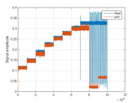
To see what happen, I send a step signal (which is real in baseband) with
different level of amplitudes (from 0.3 to 1.2 with a step of 0.1) each
step is maintained during 1e4 samples. On the receiver side, I can observe
a compression when the amplitude is close to 1. This is what I expected.
But for the values higher than 1, I can observe, periodically, a strong
decay in amplitude. I observe the same thing for an amplitude of 1.1 and
1.2 (this explains why the last step is longer)(blue signal in the figure).

I suppose that it doesn't come from the power amplifier. If it was the DAC,
I expected to only see a clipping, and thus, a constant signal in amplitude
(plus a noise).

I read that the maximum amplitude that we could use on I and Q was 1. Do
you know what happen when the amplitude of the input signal is higher than
1 on I or Q? The DAC can deliver an amplitude higher than 1?

I also sent this step signal with a phase of pi/4 (in red in the picture).
We can see that with an amplitude of 1.1 and 1.2 (thus 0.777 and 0.848 on I
and Q), that the amplitude of the step is reduced . In this case, the DAC
should give a sufficiently high amplitude. Is it possible that it comes
from the power amplifier? Why a so important reduction of the power output
in this case?

I observe similar results with different sampling frequencies.

Do you have an explanation for these results?

I hope that the results are easy to read.

Thanks in advance for your answer,

Marc
Hi everyone, I work with 2 USRP N210 and with RFX2450. They are synchroized in frequency with an external 10 MHz clock. I try to see what happen when we use them close to the saturation point of their power amplifier. The transmitted signal is defined in fc32 with: uhd::stream_args_t stream_args("fc32","sc8"); To see what happen, I send a step signal (which is real in baseband) with different level of amplitudes (from 0.3 to 1.2 with a step of 0.1) each step is maintained during 1e4 samples. On the receiver side, I can observe a compression when the amplitude is close to 1. This is what I expected. But for the values higher than 1, I can observe, periodically, a strong decay in amplitude. I observe the same thing for an amplitude of 1.1 and 1.2 (this explains why the last step is longer)(blue signal in the figure). I suppose that it doesn't come from the power amplifier. If it was the DAC, I expected to only see a clipping, and thus, a constant signal in amplitude (plus a noise). I read that the maximum amplitude that we could use on I and Q was 1. Do you know what happen when the amplitude of the input signal is higher than 1 on I or Q? The DAC can deliver an amplitude higher than 1? I also sent this step signal with a phase of pi/4 (in red in the picture). We can see that with an amplitude of 1.1 and 1.2 (thus 0.777 and 0.848 on I and Q), that the amplitude of the step is reduced . In this case, the DAC should give a sufficiently high amplitude. Is it possible that it comes from the power amplifier? Why a so important reduction of the power output in this case? I observe similar results with different sampling frequencies. Do you have an explanation for these results? I hope that the results are easy to read. Thanks in advance for your answer, Marc
MM
Marcus Müller
Thu, May 26, 2016 8:26 PM

Hi Marc,
thanks for raising this here!

Do you know what happen when the amplitude of the input signal is
higher than 1 on I or Q? The DAC can deliver an amplitude higher than 1?

Without FPGA-modifying hacks, you won't be able to send values higher
than 1 for I or Q – that 1 is converted to the maximum of your
on-the-wire format (for example, to 2**15-1 for the default SC16 format
that the N210 uses over ethernet).
The float32-to-SC16 converter takes care of the saturating arithmetics;
and even if you directly sent the 16bit integer values – the highest
value is the highest value.

So, this made me think, and here's my explanation:

Now, what might happen for complexes with |.| > 1 is that arithmetic
shenanigans take place in the DSP chain when it processes these samples.
For example, due to the digital tuning capabilities in the FPGA, your
pi/4 phase signal might be rotated back to a 0-phase signal; somewhere
in that rotation, a value will occur that is higher than the maximum
value for I or Q, and in that moment, you might see things like the
numerical value "overflowing" and suddenly being small instead of very big.

So, you really shouldn't send complex values with a magnitude larger
than 1. It will confuse the DSP chain.

Best regards,
Marcus

On 26.05.2016 22:00, Marc Bauduin via USRP-users wrote:

Hi everyone,

I work with 2 USRP N210 and with RFX2450. They are synchroized in
frequency with an external 10 MHz clock.

I try to see what happen when we use them close to the saturation
point of their power amplifier.

The transmitted signal is defined in fc32 with:
uhd::stream_args_t stream_args("fc32","sc8");

To see what happen, I send a step signal (which is real in baseband)
with different level of amplitudes (from 0.3 to 1.2 with a step of
0.1) each step is maintained during 1e4 samples. On the receiver side,
I can observe a compression when the amplitude is close to 1. This is
what I expected. But for the values higher than 1, I can observe,
periodically, a strong decay in amplitude. I observe the same thing
for an amplitude of 1.1 and 1.2 (this explains why the last step is
longer)(blue signal in the figure).

I suppose that it doesn't come from the power amplifier. If it was the
DAC, I expected to only see a clipping, and thus, a constant signal in
amplitude (plus a noise).

I read that the maximum amplitude that we could use on I and Q was 1.
Do you know what happen when the amplitude of the input signal is
higher than 1 on I or Q? The DAC can deliver an amplitude higher than 1?

I also sent this step signal with a phase of pi/4 (in red in the
picture). We can see that with an amplitude of 1.1 and 1.2 (thus 0.777
and 0.848 on I and Q), that the amplitude of the step is reduced . In
this case, the DAC should give a sufficiently high amplitude. Is it
possible that it comes from the power amplifier? Why a so important
reduction of the power output in this case?

I observe similar results with different sampling frequencies.

Do you have an explanation for these results?

I hope that the results are easy to read.

Thanks in advance for your answer,

Marc


USRP-users mailing list
USRP-users@lists.ettus.com
http://lists.ettus.com/mailman/listinfo/usrp-users_lists.ettus.com

Hi Marc, thanks for raising this here! > Do you know what happen when the amplitude of the input signal is > higher than 1 on I or Q? The DAC can deliver an amplitude higher than 1? Without FPGA-modifying hacks, you won't be able to send values higher than 1 for I or Q – that 1 is converted to the maximum of your on-the-wire format (for example, to 2**15-1 for the default SC16 format that the N210 uses over ethernet). The float32-to-SC16 converter takes care of the saturating arithmetics; and even if you directly sent the 16bit integer values – the highest value is the highest value. So, this made me think, and here's my explanation: Now, what might happen for complexes with |.| > 1 is that arithmetic shenanigans take place in the DSP chain when it processes these samples. For example, due to the digital tuning capabilities in the FPGA, your pi/4 phase signal might be rotated back to a 0-phase signal; somewhere in that rotation, a value will occur that is higher than the maximum value for I or Q, and in that moment, you might see things like the numerical value "overflowing" and suddenly being small instead of very big. So, you really shouldn't send complex values with a magnitude larger than 1. It will confuse the DSP chain. Best regards, Marcus On 26.05.2016 22:00, Marc Bauduin via USRP-users wrote: > Hi everyone, > > I work with 2 USRP N210 and with RFX2450. They are synchroized in > frequency with an external 10 MHz clock. > > I try to see what happen when we use them close to the saturation > point of their power amplifier. > > The transmitted signal is defined in fc32 with: > uhd::stream_args_t stream_args("fc32","sc8"); > > To see what happen, I send a step signal (which is real in baseband) > with different level of amplitudes (from 0.3 to 1.2 with a step of > 0.1) each step is maintained during 1e4 samples. On the receiver side, > I can observe a compression when the amplitude is close to 1. This is > what I expected. But for the values higher than 1, I can observe, > periodically, a strong decay in amplitude. I observe the same thing > for an amplitude of 1.1 and 1.2 (this explains why the last step is > longer)(blue signal in the figure). > > I suppose that it doesn't come from the power amplifier. If it was the > DAC, I expected to only see a clipping, and thus, a constant signal in > amplitude (plus a noise). > > I read that the maximum amplitude that we could use on I and Q was 1. > Do you know what happen when the amplitude of the input signal is > higher than 1 on I or Q? The DAC can deliver an amplitude higher than 1? > > I also sent this step signal with a phase of pi/4 (in red in the > picture). We can see that with an amplitude of 1.1 and 1.2 (thus 0.777 > and 0.848 on I and Q), that the amplitude of the step is reduced . In > this case, the DAC should give a sufficiently high amplitude. Is it > possible that it comes from the power amplifier? Why a so important > reduction of the power output in this case? > > I observe similar results with different sampling frequencies. > > Do you have an explanation for these results? > > I hope that the results are easy to read. > > Thanks in advance for your answer, > > Marc > > > _______________________________________________ > USRP-users mailing list > USRP-users@lists.ettus.com > http://lists.ettus.com/mailman/listinfo/usrp-users_lists.ettus.com
IB
Ian Buckley
Thu, May 26, 2016 10:06 PM

Indeed, I fixed overflow problems in intermediate stages of the DSP logic
due to complex rotation of large amplitudes only last year on newer 3
series USRP's.
I can't recall what the situation is with N210 off the top of my head, when
in doubt leave some headroom in the digital signal.
Remember also that the amplitude into the PA is dependent on programable
analog gain values in addition to digital signal amplitude, and the point
of saturation varies across daughter boards.
In general you do not need a maximum amplitude input signal to saturate the
PA with a high gain value.
In practical terms examine the quality of your digital signal first on test
equipment by pairing it with a small analog gain value that ensures you
only will see digital signal processing issues...then increase the gain to
see analog imperfections.
-Ian

On Thu, May 26, 2016 at 1:26 PM, Marcus Müller usrp-users@lists.ettus.com
wrote:

Hi Marc,
thanks for raising this here!

Do you know what happen when the amplitude of the input signal is higher
than 1 on I or Q? The DAC can deliver an amplitude higher than 1?

Without FPGA-modifying hacks, you won't be able to send values higher than
1 for I or Q – that 1 is converted to the maximum of your on-the-wire
format (for example, to 2**15-1 for the default SC16 format that the N210
uses over ethernet).
The float32-to-SC16 converter takes care of the saturating arithmetics;
and even if you directly sent the 16bit integer values – the highest value
is the highest value.

So, this made me think, and here's my explanation:

Now, what might happen for complexes with |.| > 1 is that arithmetic
shenanigans take place in the DSP chain when it processes these samples.
For example, due to the digital tuning capabilities in the FPGA, your pi/4
phase signal might be rotated back to a 0-phase signal; somewhere in that
rotation, a value will occur that is higher than the maximum value for I or
Q, and in that moment, you might see things like the numerical value
"overflowing" and suddenly being small instead of very big.

So, you really shouldn't send complex values with a magnitude larger than

  1. It will confuse the DSP chain.

Best regards,
Marcus

On 26.05.2016 22:00, Marc Bauduin via USRP-users wrote:

Hi everyone,

I work with 2 USRP N210 and with RFX2450. They are synchroized in
frequency with an external 10 MHz clock.

I try to see what happen when we use them close to the saturation point of
their power amplifier.

The transmitted signal is defined in fc32 with:
uhd::stream_args_t stream_args("fc32","sc8");

To see what happen, I send a step signal (which is real in baseband) with
different level of amplitudes (from 0.3 to 1.2 with a step of 0.1) each
step is maintained during 1e4 samples. On the receiver side, I can observe
a compression when the amplitude is close to 1. This is what I expected.
But for the values higher than 1, I can observe, periodically, a strong
decay in amplitude. I observe the same thing for an amplitude of 1.1 and
1.2 (this explains why the last step is longer)(blue signal in the figure).

I suppose that it doesn't come from the power amplifier. If it was the
DAC, I expected to only see a clipping, and thus, a constant signal in
amplitude (plus a noise).

I read that the maximum amplitude that we could use on I and Q was 1. Do
you know what happen when the amplitude of the input signal is higher than
1 on I or Q? The DAC can deliver an amplitude higher than 1?

I also sent this step signal with a phase of pi/4 (in red in the picture).
We can see that with an amplitude of 1.1 and 1.2 (thus 0.777 and 0.848 on I
and Q), that the amplitude of the step is reduced . In this case, the DAC
should give a sufficiently high amplitude. Is it possible that it comes
from the power amplifier? Why a so important reduction of the power output
in this case?

I observe similar results with different sampling frequencies.

Do you have an explanation for these results?

I hope that the results are easy to read.

Thanks in advance for your answer,

Marc


USRP-users mailing listUSRP-users@lists.ettus.comhttp://lists.ettus.com/mailman/listinfo/usrp-users_lists.ettus.com


USRP-users mailing list
USRP-users@lists.ettus.com
http://lists.ettus.com/mailman/listinfo/usrp-users_lists.ettus.com

Indeed, I fixed overflow problems in intermediate stages of the DSP logic due to complex rotation of large amplitudes only last year on newer 3 series USRP's. I can't recall what the situation is with N210 off the top of my head, when in doubt leave some headroom in the digital signal. Remember also that the amplitude into the PA is dependent on programable analog gain values in addition to digital signal amplitude, and the point of saturation varies across daughter boards. In general you do not need a maximum amplitude input signal to saturate the PA with a high gain value. In practical terms examine the quality of your digital signal first on test equipment by pairing it with a small analog gain value that ensures you only will see digital signal processing issues...then increase the gain to see analog imperfections. -Ian On Thu, May 26, 2016 at 1:26 PM, Marcus Müller <usrp-users@lists.ettus.com> wrote: > Hi Marc, > thanks for raising this here! > > Do you know what happen when the amplitude of the input signal is higher > than 1 on I or Q? The DAC can deliver an amplitude higher than 1? > > Without FPGA-modifying hacks, you won't be able to send values higher than > 1 for I or Q – that 1 is converted to the maximum of your on-the-wire > format (for example, to 2**15-1 for the default SC16 format that the N210 > uses over ethernet). > The float32-to-SC16 converter takes care of the saturating arithmetics; > and even if you directly sent the 16bit integer values – the highest value > is the highest value. > > So, this made me think, and here's my explanation: > > Now, what might happen for complexes with |.| > 1 is that arithmetic > shenanigans take place in the DSP chain when it processes these samples. > For example, due to the digital tuning capabilities in the FPGA, your pi/4 > phase signal might be rotated back to a 0-phase signal; somewhere in that > rotation, a value will occur that is higher than the maximum value for I or > Q, and in that moment, you might see things like the numerical value > "overflowing" and suddenly being small instead of very big. > > So, you really shouldn't send complex values with a magnitude larger than > 1. It will confuse the DSP chain. > > Best regards, > Marcus > > > On 26.05.2016 22:00, Marc Bauduin via USRP-users wrote: > > Hi everyone, > > I work with 2 USRP N210 and with RFX2450. They are synchroized in > frequency with an external 10 MHz clock. > > I try to see what happen when we use them close to the saturation point of > their power amplifier. > > The transmitted signal is defined in fc32 with: > uhd::stream_args_t stream_args("fc32","sc8"); > > To see what happen, I send a step signal (which is real in baseband) with > different level of amplitudes (from 0.3 to 1.2 with a step of 0.1) each > step is maintained during 1e4 samples. On the receiver side, I can observe > a compression when the amplitude is close to 1. This is what I expected. > But for the values higher than 1, I can observe, periodically, a strong > decay in amplitude. I observe the same thing for an amplitude of 1.1 and > 1.2 (this explains why the last step is longer)(blue signal in the figure). > > I suppose that it doesn't come from the power amplifier. If it was the > DAC, I expected to only see a clipping, and thus, a constant signal in > amplitude (plus a noise). > > I read that the maximum amplitude that we could use on I and Q was 1. Do > you know what happen when the amplitude of the input signal is higher than > 1 on I or Q? The DAC can deliver an amplitude higher than 1? > > I also sent this step signal with a phase of pi/4 (in red in the picture). > We can see that with an amplitude of 1.1 and 1.2 (thus 0.777 and 0.848 on I > and Q), that the amplitude of the step is reduced . In this case, the DAC > should give a sufficiently high amplitude. Is it possible that it comes > from the power amplifier? Why a so important reduction of the power output > in this case? > > I observe similar results with different sampling frequencies. > > Do you have an explanation for these results? > > I hope that the results are easy to read. > > Thanks in advance for your answer, > > Marc > > > _______________________________________________ > USRP-users mailing listUSRP-users@lists.ettus.comhttp://lists.ettus.com/mailman/listinfo/usrp-users_lists.ettus.com > > > > _______________________________________________ > USRP-users mailing list > USRP-users@lists.ettus.com > http://lists.ettus.com/mailman/listinfo/usrp-users_lists.ettus.com > >
MB
Marc Bauduin
Fri, May 27, 2016 9:26 AM

Thank you for your answers.

The RFX2450 have a fixed gain. So I cannot increase the gain to saturate
the PA.

Marc

2016-05-27 0:06 GMT+02:00 Ian Buckley via USRP-users <
usrp-users@lists.ettus.com>:

Indeed, I fixed overflow problems in intermediate stages of the DSP logic
due to complex rotation of large amplitudes only last year on newer 3
series USRP's.
I can't recall what the situation is with N210 off the top of my head,
when in doubt leave some headroom in the digital signal.
Remember also that the amplitude into the PA is dependent on programable
analog gain values in addition to digital signal amplitude, and the point
of saturation varies across daughter boards.
In general you do not need a maximum amplitude input signal to saturate
the PA with a high gain value.
In practical terms examine the quality of your digital signal first on
test equipment by pairing it with a small analog gain value that ensures
you only will see digital signal processing issues...then increase the gain
to see analog imperfections.
-Ian

On Thu, May 26, 2016 at 1:26 PM, Marcus Müller <usrp-users@lists.ettus.com

wrote:

Hi Marc,
thanks for raising this here!

Do you know what happen when the amplitude of the input signal is higher
than 1 on I or Q? The DAC can deliver an amplitude higher than 1?

Without FPGA-modifying hacks, you won't be able to send values higher
than 1 for I or Q – that 1 is converted to the maximum of your on-the-wire
format (for example, to 2**15-1 for the default SC16 format that the N210
uses over ethernet).
The float32-to-SC16 converter takes care of the saturating arithmetics;
and even if you directly sent the 16bit integer values – the highest value
is the highest value.

So, this made me think, and here's my explanation:

Now, what might happen for complexes with |.| > 1 is that arithmetic
shenanigans take place in the DSP chain when it processes these samples.
For example, due to the digital tuning capabilities in the FPGA, your pi/4
phase signal might be rotated back to a 0-phase signal; somewhere in that
rotation, a value will occur that is higher than the maximum value for I or
Q, and in that moment, you might see things like the numerical value
"overflowing" and suddenly being small instead of very big.

So, you really shouldn't send complex values with a magnitude larger than

  1. It will confuse the DSP chain.

Best regards,
Marcus

On 26.05.2016 22:00, Marc Bauduin via USRP-users wrote:

Hi everyone,

I work with 2 USRP N210 and with RFX2450. They are synchroized in
frequency with an external 10 MHz clock.

I try to see what happen when we use them close to the saturation point
of their power amplifier.

The transmitted signal is defined in fc32 with:
uhd::stream_args_t stream_args("fc32","sc8");

To see what happen, I send a step signal (which is real in baseband) with
different level of amplitudes (from 0.3 to 1.2 with a step of 0.1) each
step is maintained during 1e4 samples. On the receiver side, I can observe
a compression when the amplitude is close to 1. This is what I expected.
But for the values higher than 1, I can observe, periodically, a strong
decay in amplitude. I observe the same thing for an amplitude of 1.1 and
1.2 (this explains why the last step is longer)(blue signal in the figure).

I suppose that it doesn't come from the power amplifier. If it was the
DAC, I expected to only see a clipping, and thus, a constant signal in
amplitude (plus a noise).

I read that the maximum amplitude that we could use on I and Q was 1. Do
you know what happen when the amplitude of the input signal is higher than
1 on I or Q? The DAC can deliver an amplitude higher than 1?

I also sent this step signal with a phase of pi/4 (in red in the
picture). We can see that with an amplitude of 1.1 and 1.2 (thus 0.777 and
0.848 on I and Q), that the amplitude of the step is reduced . In this
case, the DAC should give a sufficiently high amplitude. Is it possible
that it comes from the power amplifier? Why a so important reduction of the
power output in this case?

I observe similar results with different sampling frequencies.

Do you have an explanation for these results?

I hope that the results are easy to read.

Thanks in advance for your answer,

Marc


USRP-users mailing listUSRP-users@lists.ettus.comhttp://lists.ettus.com/mailman/listinfo/usrp-users_lists.ettus.com


USRP-users mailing list
USRP-users@lists.ettus.com
http://lists.ettus.com/mailman/listinfo/usrp-users_lists.ettus.com

Thank you for your answers. The RFX2450 have a fixed gain. So I cannot increase the gain to saturate the PA. Marc 2016-05-27 0:06 GMT+02:00 Ian Buckley via USRP-users < usrp-users@lists.ettus.com>: > Indeed, I fixed overflow problems in intermediate stages of the DSP logic > due to complex rotation of large amplitudes only last year on newer 3 > series USRP's. > I can't recall what the situation is with N210 off the top of my head, > when in doubt leave some headroom in the digital signal. > Remember also that the amplitude into the PA is dependent on programable > analog gain values in addition to digital signal amplitude, and the point > of saturation varies across daughter boards. > In general you do not need a maximum amplitude input signal to saturate > the PA with a high gain value. > In practical terms examine the quality of your digital signal first on > test equipment by pairing it with a small analog gain value that ensures > you only will see digital signal processing issues...then increase the gain > to see analog imperfections. > -Ian > > > On Thu, May 26, 2016 at 1:26 PM, Marcus Müller <usrp-users@lists.ettus.com > > wrote: > >> Hi Marc, >> thanks for raising this here! >> >> Do you know what happen when the amplitude of the input signal is higher >> than 1 on I or Q? The DAC can deliver an amplitude higher than 1? >> >> Without FPGA-modifying hacks, you won't be able to send values higher >> than 1 for I or Q – that 1 is converted to the maximum of your on-the-wire >> format (for example, to 2**15-1 for the default SC16 format that the N210 >> uses over ethernet). >> The float32-to-SC16 converter takes care of the saturating arithmetics; >> and even if you directly sent the 16bit integer values – the highest value >> is the highest value. >> >> So, this made me think, and here's my explanation: >> >> Now, what might happen for complexes with |.| > 1 is that arithmetic >> shenanigans take place in the DSP chain when it processes these samples. >> For example, due to the digital tuning capabilities in the FPGA, your pi/4 >> phase signal might be rotated back to a 0-phase signal; somewhere in that >> rotation, a value will occur that is higher than the maximum value for I or >> Q, and in that moment, you might see things like the numerical value >> "overflowing" and suddenly being small instead of very big. >> >> So, you really shouldn't send complex values with a magnitude larger than >> 1. It will confuse the DSP chain. >> >> Best regards, >> Marcus >> >> >> On 26.05.2016 22:00, Marc Bauduin via USRP-users wrote: >> >> Hi everyone, >> >> I work with 2 USRP N210 and with RFX2450. They are synchroized in >> frequency with an external 10 MHz clock. >> >> I try to see what happen when we use them close to the saturation point >> of their power amplifier. >> >> The transmitted signal is defined in fc32 with: >> uhd::stream_args_t stream_args("fc32","sc8"); >> >> To see what happen, I send a step signal (which is real in baseband) with >> different level of amplitudes (from 0.3 to 1.2 with a step of 0.1) each >> step is maintained during 1e4 samples. On the receiver side, I can observe >> a compression when the amplitude is close to 1. This is what I expected. >> But for the values higher than 1, I can observe, periodically, a strong >> decay in amplitude. I observe the same thing for an amplitude of 1.1 and >> 1.2 (this explains why the last step is longer)(blue signal in the figure). >> >> I suppose that it doesn't come from the power amplifier. If it was the >> DAC, I expected to only see a clipping, and thus, a constant signal in >> amplitude (plus a noise). >> >> I read that the maximum amplitude that we could use on I and Q was 1. Do >> you know what happen when the amplitude of the input signal is higher than >> 1 on I or Q? The DAC can deliver an amplitude higher than 1? >> >> I also sent this step signal with a phase of pi/4 (in red in the >> picture). We can see that with an amplitude of 1.1 and 1.2 (thus 0.777 and >> 0.848 on I and Q), that the amplitude of the step is reduced . In this >> case, the DAC should give a sufficiently high amplitude. Is it possible >> that it comes from the power amplifier? Why a so important reduction of the >> power output in this case? >> >> I observe similar results with different sampling frequencies. >> >> Do you have an explanation for these results? >> >> I hope that the results are easy to read. >> >> Thanks in advance for your answer, >> >> Marc >> >> >> _______________________________________________ >> USRP-users mailing listUSRP-users@lists.ettus.comhttp://lists.ettus.com/mailman/listinfo/usrp-users_lists.ettus.com >> >> >> >> _______________________________________________ >> USRP-users mailing list >> USRP-users@lists.ettus.com >> http://lists.ettus.com/mailman/listinfo/usrp-users_lists.ettus.com >> >> > > _______________________________________________ > USRP-users mailing list > USRP-users@lists.ettus.com > http://lists.ettus.com/mailman/listinfo/usrp-users_lists.ettus.com > >
MM
Marcus Müller
Fri, May 27, 2016 11:08 AM

Hi Marc,

having had another look at your plot: This is most definitely digital,
and if this really happens only for complex values with magnitudes > 1,
well, don't use those :)

I must admit that I can see why UHD doesn't ensure that on the host side
(calculate magnitude or magnitude squared is pretty CPU-intense), and I
also must admit that solving this the Buckley way :) in the FPGA was the
right thing to do for gen3 devices; now, on gen2, I think
application-side multiplication with 1/sqrt(2) will probably be the
safest way to avoid this problem, and considering the fact that you'd
end up with a value that wouldn't lead to more power output even if the
FPGA did the saturating math, you wouldn't even lose TX power.

Best regards,
Marcus

On 27.05.2016 11:26, Marc Bauduin wrote:

Thank you for your answers.

The RFX2450 have a fixed gain. So I cannot increase the gain to
saturate the PA.

Marc

2016-05-27 0:06 GMT+02:00 Ian Buckley via USRP-users
<usrp-users@lists.ettus.com mailto:usrp-users@lists.ettus.com>:

 Indeed, I fixed overflow problems in intermediate stages of the
 DSP logic due to complex rotation of large amplitudes only last
 year on newer 3 series USRP's.
 I can't recall what the situation is with N210 off the top of my
 head, when in doubt leave some headroom in the digital signal. 
 Remember also that the amplitude into the PA is dependent on
 programable analog gain values in addition to digital signal
 amplitude, and the point of saturation varies across daughter boards.
 In general you do not need a maximum amplitude input signal to
 saturate the PA with a high gain value.
 In practical terms examine the quality of your digital signal
 first on test equipment by pairing it with a small analog gain
 value that ensures you only will see digital signal processing
 issues...then increase the gain to see analog imperfections.
 -Ian


 On Thu, May 26, 2016 at 1:26 PM, Marcus Müller
 <usrp-users@lists.ettus.com <mailto:usrp-users@lists.ettus.com>>
 wrote:

     Hi Marc,
     thanks for raising this here!
     Do you know what happen when the amplitude of the input
     signal is higher than 1 on I or Q? The DAC can deliver an
     amplitude higher than 1?
     Without FPGA-modifying hacks, you won't be able to send values
     higher than 1 for I or Q – that 1 is converted to the maximum
     of your on-the-wire format (for example, to 2**15-1 for the
     default SC16 format that the N210 uses over ethernet).
     The float32-to-SC16 converter takes care of the saturating
     arithmetics; and even if you directly sent the 16bit integer
     values – the highest value is the highest value.

     So, this made me think, and here's my explanation:

     Now, what might happen for complexes with |.| > 1 is that
     arithmetic shenanigans take place in the DSP chain when it
     processes these samples. For example, due to the digital
     tuning capabilities in the FPGA, your pi/4 phase signal might
     be rotated back to a 0-phase signal; somewhere in that
     rotation, a value will occur that is higher than the maximum
     value for I or Q, and in that moment, you might see things
     like the numerical value "overflowing" and suddenly being
     small instead of very big.

     So, you really shouldn't send complex values with a magnitude
     larger than 1. It will confuse the DSP chain.

     Best regards,
     Marcus


     On 26.05.2016 22:00, Marc Bauduin via USRP-users wrote:
     Hi everyone,

     I work with 2 USRP N210 and with RFX2450. They are
     synchroized in frequency with an external 10 MHz clock.

     I try to see what happen when we use them close to the
     saturation point of their power amplifier.

     The transmitted signal is defined in fc32 with:
     uhd::stream_args_t stream_args("fc32","sc8"); 

     To see what happen, I send a step signal (which is real in
     baseband) with different level of amplitudes (from 0.3 to 1.2
     with a step of 0.1) each step is maintained during 1e4
     samples. On the receiver side, I can observe a compression
     when the amplitude is close to 1. This is what I expected.
     But for the values higher than 1, I can observe,
     periodically, a strong decay in amplitude. I observe the same
     thing for an amplitude of 1.1 and 1.2 (this explains why the
     last step is longer)(blue signal in the figure).

     I suppose that it doesn't come from the power amplifier. If
     it was the DAC, I expected to only see a clipping, and thus,
     a constant signal in amplitude (plus a noise).

     I read that the maximum amplitude that we could use on I and
     Q was 1. Do you know what happen when the amplitude of the
     input signal is higher than 1 on I or Q? The DAC can deliver
     an amplitude higher than 1?

     I also sent this step signal with a phase of pi/4 (in red in
     the picture). We can see that with an amplitude of 1.1 and
     1.2 (thus 0.777 and 0.848 on I and Q), that the amplitude of
     the step is reduced . In this case, the DAC should give a
     sufficiently high amplitude. Is it possible that it comes
     from the power amplifier? Why a so important reduction of the
     power output in this case?

     I observe similar results with different sampling frequencies.

     Do you have an explanation for these results?

     I hope that the results are easy to read.

     Thanks in advance for your answer,

     Marc


     _______________________________________________
     USRP-users mailing list
     USRP-users@lists.ettus.com <mailto:USRP-users@lists.ettus.com>
     http://lists.ettus.com/mailman/listinfo/usrp-users_lists.ettus.com
     _______________________________________________
     USRP-users mailing list
     USRP-users@lists.ettus.com <mailto:USRP-users@lists.ettus.com>
     http://lists.ettus.com/mailman/listinfo/usrp-users_lists.ettus.com


 _______________________________________________
 USRP-users mailing list
 USRP-users@lists.ettus.com <mailto:USRP-users@lists.ettus.com>
 http://lists.ettus.com/mailman/listinfo/usrp-users_lists.ettus.com
Hi Marc, having had another look at your plot: This is most definitely digital, and if this really happens only for complex values with magnitudes > 1, well, don't use those :) I must admit that I can see why UHD doesn't ensure that on the host side (calculate magnitude or magnitude squared is pretty CPU-intense), and I also must admit that solving this the Buckley way :) in the FPGA was the right thing to do for gen3 devices; now, on gen2, I think application-side multiplication with 1/sqrt(2) will probably be the safest way to avoid this problem, and considering the fact that you'd end up with a value that wouldn't lead to more power output even if the FPGA did the saturating math, you wouldn't even lose TX power. Best regards, Marcus On 27.05.2016 11:26, Marc Bauduin wrote: > Thank you for your answers. > > The RFX2450 have a fixed gain. So I cannot increase the gain to > saturate the PA. > > Marc > > 2016-05-27 0:06 GMT+02:00 Ian Buckley via USRP-users > <usrp-users@lists.ettus.com <mailto:usrp-users@lists.ettus.com>>: > > Indeed, I fixed overflow problems in intermediate stages of the > DSP logic due to complex rotation of large amplitudes only last > year on newer 3 series USRP's. > I can't recall what the situation is with N210 off the top of my > head, when in doubt leave some headroom in the digital signal. > Remember also that the amplitude into the PA is dependent on > programable analog gain values in addition to digital signal > amplitude, and the point of saturation varies across daughter boards. > In general you do not need a maximum amplitude input signal to > saturate the PA with a high gain value. > In practical terms examine the quality of your digital signal > first on test equipment by pairing it with a small analog gain > value that ensures you only will see digital signal processing > issues...then increase the gain to see analog imperfections. > -Ian > > > On Thu, May 26, 2016 at 1:26 PM, Marcus Müller > <usrp-users@lists.ettus.com <mailto:usrp-users@lists.ettus.com>> > wrote: > > Hi Marc, > thanks for raising this here! > >> Do you know what happen when the amplitude of the input >> signal is higher than 1 on I or Q? The DAC can deliver an >> amplitude higher than 1? > Without FPGA-modifying hacks, you won't be able to send values > higher than 1 for I or Q – that 1 is converted to the maximum > of your on-the-wire format (for example, to 2**15-1 for the > default SC16 format that the N210 uses over ethernet). > The float32-to-SC16 converter takes care of the saturating > arithmetics; and even if you directly sent the 16bit integer > values – the highest value is the highest value. > > So, this made me think, and here's my explanation: > > Now, what might happen for complexes with |.| > 1 is that > arithmetic shenanigans take place in the DSP chain when it > processes these samples. For example, due to the digital > tuning capabilities in the FPGA, your pi/4 phase signal might > be rotated back to a 0-phase signal; somewhere in that > rotation, a value will occur that is higher than the maximum > value for I or Q, and in that moment, you might see things > like the numerical value "overflowing" and suddenly being > small instead of very big. > > So, you really shouldn't send complex values with a magnitude > larger than 1. It will confuse the DSP chain. > > Best regards, > Marcus > > > On 26.05.2016 22:00, Marc Bauduin via USRP-users wrote: >> Hi everyone, >> >> I work with 2 USRP N210 and with RFX2450. They are >> synchroized in frequency with an external 10 MHz clock. >> >> I try to see what happen when we use them close to the >> saturation point of their power amplifier. >> >> The transmitted signal is defined in fc32 with: >> uhd::stream_args_t stream_args("fc32","sc8"); >> >> To see what happen, I send a step signal (which is real in >> baseband) with different level of amplitudes (from 0.3 to 1.2 >> with a step of 0.1) each step is maintained during 1e4 >> samples. On the receiver side, I can observe a compression >> when the amplitude is close to 1. This is what I expected. >> But for the values higher than 1, I can observe, >> periodically, a strong decay in amplitude. I observe the same >> thing for an amplitude of 1.1 and 1.2 (this explains why the >> last step is longer)(blue signal in the figure). >> >> I suppose that it doesn't come from the power amplifier. If >> it was the DAC, I expected to only see a clipping, and thus, >> a constant signal in amplitude (plus a noise). >> >> I read that the maximum amplitude that we could use on I and >> Q was 1. Do you know what happen when the amplitude of the >> input signal is higher than 1 on I or Q? The DAC can deliver >> an amplitude higher than 1? >> >> I also sent this step signal with a phase of pi/4 (in red in >> the picture). We can see that with an amplitude of 1.1 and >> 1.2 (thus 0.777 and 0.848 on I and Q), that the amplitude of >> the step is reduced . In this case, the DAC should give a >> sufficiently high amplitude. Is it possible that it comes >> from the power amplifier? Why a so important reduction of the >> power output in this case? >> >> I observe similar results with different sampling frequencies. >> >> Do you have an explanation for these results? >> >> I hope that the results are easy to read. >> >> Thanks in advance for your answer, >> >> Marc >> >> >> _______________________________________________ >> USRP-users mailing list >> USRP-users@lists.ettus.com <mailto:USRP-users@lists.ettus.com> >> http://lists.ettus.com/mailman/listinfo/usrp-users_lists.ettus.com > > > _______________________________________________ > USRP-users mailing list > USRP-users@lists.ettus.com <mailto:USRP-users@lists.ettus.com> > http://lists.ettus.com/mailman/listinfo/usrp-users_lists.ettus.com > > > > _______________________________________________ > USRP-users mailing list > USRP-users@lists.ettus.com <mailto:USRP-users@lists.ettus.com> > http://lists.ettus.com/mailman/listinfo/usrp-users_lists.ettus.com > >